CERAMIC FORMULATION FOR THE IMMOBILIZATION
OF PLUTONIUM
Bartley B. Ebbinghaus, Richard A. VanKonynenburg, and Frederick J.
Ryerson
Lawrence Livermore National Laboratory
Eric R. "Lou" Vance, Martin W. A. Stewart, and Adam Jostsons
Australian Nuclear Science and Technology Organization
Jeffrey S. Allender, Thomas Rankin, and James Congdon
Westinghouse Savannah River Company
ABSTRACT
Between 8 and 50 metric tons of excess Pu is currently planned to be dispositioned by immobilization in a ceramic matrix followed by encapsulation in high-level nuclear waste glass. This process will render the Pu undesirable for theft, diversion, or reuse in weapons. The ceramic form is based on a family of titanate-based ceramic forms called Synroc which is short for "synthetic rock." These forms are based on natural mineral analogs that have survived for hundreds of millions of years in wet environments. The form has been tailored to incorporate a wide range of Pu and U and sufficient neutron absorber (Hf and Gd) to eliminate criticality concerns in the repository. The baseline form is composed primarily of pyrochlore and lesser amounts of zirconolite, brannerite, and rutile. The form has been shown to meet or exceed all of the desirable characteristics of a Pu immobilization form, thus making it a viable and attractive candidate for the Pu disposition mission.
INTRODUCTION
In the fall of 1997, after a detailed review of the glass and ceramic plutonium disposition options, the U.S. Department of Energy Office of Fissile Materials Disposition chose to focus its future Pu immobilization efforts on a ceramic immobilization form. The lead laboratory for this work is the Lawrence Livermore National Laboratory (LLNL), and significant roles in the effort are played by the Savannah River Site (SRS), the Argonne National Laboratory (ANL), the Pacific Northwest National Laboratory (PNNL), the Australian Nuclear Science and Technology Organization (ANSTO), and several university groups. The D.O.E.-preferred physical configuration is the so-called "can-in-canister" approach, in which Pu would be incorporated into ceramic disks, which would then be stacked inside cans about 7.6 cm in diameter. These cans in turn would be loaded into the pour canisters at the Defense Waste Processing Facility (DWPF) for High Level Waste (HLW) glass, and the molten glass would be poured in around them to provide an external gamma radiation barrier. The massive monoliths with encapsulated Pu-bearing ceramics are then believed to be a less attractive target for Pu extraction and purification than the larger inventory of Pu in spent fuel, thus meeting the so called "Spent Fuel Standard."
Desirable characteristics for a ceramic to immobilize Pu include (1) fabricability by a process that is reliable, safe, reasonable in cost, and demonstrated at a production scale with similar materials; (2) ability to incorporate "high-fired" PuO2 of a particle size greater than about 10 micrometers; (3) sufficient compositional flexibility to incorporate significant concentrations of Pu and neutron absorbers (Gd and Hf) as well as varying impurities in the feed streams; (4) thermal stability during the glass pouring operation for the can-in-canister configuration; (5) high chemical durability in geologic repository environments both before and after undergoing radiation damage from alpha decay; (6) availability of natural mineral analogs that have successfully immobilized actinides for geologic time periods; and (7) difficult recoverability of Pu, thereby promoting nonproliferation.
In response to these needs, the ceramic form for Pu immobilization was chosen based on the broad experience with the titanate-based Synroc family of ceramic waste forms, developed primarily for various types of high-level nuclear waste over the past 20 years1. Because of the simultaneous needs to achieve high Pu loading as well as to incorporate significant quantities of U, which is found in many of the Pu feed streams, and the neutron absorbers, a cubic mineral phase called pyrochlore (nominally A2Ti2O7, where A represents a range of ions, including Ca, Gd, Hf, U, and Pu) has been chosen as the primary phase in the ceramic form. The pyrochlore structure is closely related to zirconolite, but has the advantage that it is able to incorporate larger concentrations of actinides and rare earths. In addition to pyrochlore, the ceramic form contains smaller amounts of zirconolite, brannerite, and rutile. This formulation is similar to those proposed by Kesson and Ringwood2 and by Solomah, et al.3 for various actinide-rich HLW solutions.
APPROACH
The approach in the ceramic formulation work was to focus the experimental work in 4 primary areas of technical concern: (1) Baseline formulation chemistry, (2) Actinide oxide dissolution kinetics, (3) Feed impurity tolerances, and (4) Stability with respect to the DWPF pour. These technical areas address items (2), (3), and (4) from the previously mentioned list of desirable characteristics. The goal of the "Baseline formulation chemistry" work was to identify the equilibrium phases and compositions in the baseline form and to demonstrate that the form could accommodate a sufficient quantity of neutron absorbers (Hf and Gd) and a wide range of Pu and/or U. The goal of the "Actinide oxide dissolution kinetics" work was to demonstrate that "high-fired" PuO2 greater than about 10 microns diameter (of less concern for respirables) could be satisfactorily incorporated into the ceramic. The goal of the "Feed impurity tolerances" work was to demonstrate that the ceramic form could accommodate the entire range of feed impurities expected in the anticipated PuO2 feed streams. The goal of the "Stability with respect to the DWPF pour" work was to show that there was no effect on the form due to the thermal treatment that will occur when molten HLW glass is poured onto the cans containing the ceramic forms.
EXPERIMENTAL
In developing formulations for Pu immobilization, Ce is used as a stand-in for Pu to reduce cost, speed up development, and allow for the use of processing and analytical equipment from which Pu work in the near term is excluded. In this manner, the follow-on Pu work is largely confirmational in nature. For 4+ Pu and Ce, the ionic radii and melting points of the oxides are almost identical, thus indicating that the crystal chemical behavior should be almost identical. The 4+ Ce only differs significantly from the 4+ Pu in that the 4+ Ce is easier to reduce to 3+ Ce than 4+ Pu is to reduce to 3+ Pu. However, both Pu and Ce are predominately in the 4+ oxidation state under the processing conditions used in this work (argon, air, or occasionally 5% CO/CO2).
The fabrication process used is cold pressing and reaction-sintering, which was first demonstrated for the Synroc waste forms by Solomah, et al.4 The starting materials are research-grade oxide powders (hydroxide powder, in the case of Ca) in the micrometer size range. The composition of the baseline ceramic (in weight %) is as follows: CaO-10.0; TiO2-35.8; HfO2-10.6; Gd2O3-8.0; UO2-23.7; and PuO2-11.9. Note that the anatase form of TiO2 is used. These powders are wet-mixed for one hour using a ball mill with Al2O3 or ZrO2 grinding media and deionized water. They are then separated by sieving and flushing with water and are dried overnight at about 90° C in air. The dried powder is then calcined at 750° C for one hour in either argon or air atmosphere. It is then cold-pressed in a steel die at about 80 MPa into cylindrical pellets, typically 12.7 mm in diameter, with length-to-diameter ratio less than one. Between pressings, the steel die is coated with a thin layer of about 10 wt % oleic acid in acetone as a die lubricant. No binders are used. (Note that larger ceramic discs about 6.7 cm diameter are to be fabricated in actual production.) The pellets are placed on platinum foil (recent practice) or on a thin layer of alumina or zirconia powder (earlier practice) and are then reaction-sintered in argon atmosphere (commercial purity) at 1350° C for 4 hours. Some samples are fired in air atmosphere or 5% CO in a balance of CO2. The fired densities are routinely evaluated using weight and geometric size, and are typically 90% of the calculated theoretical maximum density or higher. Phase composition is routinely evaluated by X-ray diffraction analysis (XRD) and scanning electron microscopy (SEM)—energy dispersive X-ray spectroscopy (EDS). Detailed analysis by electron microprobe is performed on select samples.
RESULTS
Baseline Formulation Chemistry
The pyrochlore-based baseline product form is observed to be composed of about 80 vol % pyrochlore, about 12 vol % brannerite, and about 8 vol % rutile. Zirconolite can also be present, but it is not generally observed when the sample is well reacted and when there are no feed impurities present. As mentioned earlier, pyrochlore and zirconolite are very closely related minerals. The primary difference in the structures arises from the way the characteristic layers of TiO2 octahedra are stacked. Zirconolite actually has several structural polytypes that also differ in the way the characteristic layers are stacked5,6: zirconolite-2M, zirconolite-3T, and zirconolite-4M (polymignyte) to name those that have actually been observed in this ceramic form. The number corresponds to the number of layers before the stacking repeats itself (2, 3, or 4) and the letter stands for the crystal symmetry, M for monoclinic and T for tetragonal. When the immediately adjacent layers are aligned, the pyrochlore phase is formed. Using the same methodology for describing the zirconolite polytypes, the pyrochlore structure is then just a symmetric form of zirconolite.
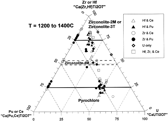
The phase relationship between pyrochlore and zirconolite and its polytypes is one important part of defining the baseline formulation. To depict the phase relationships, a pseudo-ternary diagram is given in Figure 1. The end points are zirconolite (CaZrTi2O7 or CaHfTi2O7), Pu-pyrochlore (CaPuTi2O7 or CaCeTi2O7), and U-pyrochlore (CaUTi2O7). The open points are data from Ce-loaded samples, and the solid points are data from the Pu-loaded samples. The squares contain Hf and Zr and the diamonds contain U only. The circles are data from the Zr-loaded samples, and the triangles are from the Hf-loaded samples. Many of the samples contain Gd, which had to be factored out in order to depict all the data on one ternary diagram. For simplicity the Gd was all assumed to be entirely on the Ca site, which is accurate in many cases. As a result of this assumption, Figure 1 is more correctly described as a ternary plot consisting of the three components, (1) Pu or Ce, (2) Hf or Zr, and (3) U. The baseline composition in this diagram is at approximately 0.49 units of U, 0.25 units of Pu, and 0.26 units of Hf.

Figure 1. Phase boundaries in the system Ca(Hf,Zr)Ti2O7-Ca(Pu,Ce)Ti2O7-CaUTi2O7.
Figure 1 clearly shows that the equilibrium phase behavior of Hf and Zr and of Ce and Pu is for all practical purposes indistinguishable. Closer inspection reveals that the equilibrium phase behavior of U is also identical to that of Ce and Pu, i.e. the pyrochlore phase boundary is independent of the total U, Pu, and Ce composition. Note that with a comparable offset adjustment in the U-loading, the Pu-loading in the form can be adjusted anywhere from 0 to about 32% without appreciably changing the mineralogy in the baseline form. The regime above 0.7 units of Ce, Pu, and U is the pyrochlore single phase regime. The region above about 0.8 units of Hf and Zr is the single phase zirconolite regime (either zirconolite-2M or -3T). There is some scatter in the zirconolite boundary. This is due at least in part to a temperature effect. At around 1400° C, the boundary appears to be closer to about 0.75 formula units, and at around 1200° C, the boundary appears to be closer to about 0.85 formula units. An intermediate phase sometimes occurs at about 0.5 formula units of Hf or Zr. This is the zirconolite-4M phase. So far it has not been observed in any samples with Pu and Hf. The reason why this phase is only observed in some samples is not yet known.
Microprobe analysis on a number of samples has been averaged to give the nominal atomic compositions of the primary phases in the ceramic form. The nominal atomic compositions are given in Table I. For zirconolite and pyrochlore, the total metal composition is normalized to 4. For brannerite, the total metal composition is normalized to 3, and for rutile and actinide oxide, it is normalized to unity. The corresponding amount of oxygen based on the assumed oxidation states shown is given in the O equivalent column. In the ideal structures, the oxygen equivalents for pyrochlore, zirconolite, brannerite, rutile, and actinide oxide are 7, 7, 6, 2, and 2, respectively.
Table I. Elemental Compositions in Baseline Form
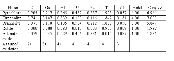
One of the interesting features in the compositions shown in Table I is that although the phase boundaries appear to be unaffected between the use of UO2 or PuO2 in the formulation, the elemental partitioning between the phases is different. Notice that U is enriched relative to Pu in the brannerite phase and depleted relative to Pu in the zirconolite phase. These enriched and depleted relationships are in comparison to the approximate 2-to-1 ratio of U-to-Pu in the dominant pyrochlore phase.
Actinide Oxide Dissolution Kinetics
Dissolution of "high-fired" PuO2 or PuO2/UO2 into the ceramic form seems to be affected significantly by temperature and process impurities, and to a lesser extent by the relative abundance of the primary phases. Note that all "high-fired" PuO2 used in these tests was heated to 1000° C for 4 hours in an air atmosphere and all the "high-fired" PuO2/UO2 was heated to 950° C for 2 hours in an argon atmosphere.
In earlier formulation work, a zirconolite-rich formulation was being developed. In addition to the matrix phase of zirconolite, the form contained Ba-hollandite, rutile, and pyrochlore. In this set of experiments performed at LLNL, the "high-fired" PuO2 was sieved through a 600 mesh sieve (i.e., less than 20 microns diameter) and the precursors were then dry mixed by hand in a V-shaped mixer. A half dozen pellets were pressed at between 30 and 80 MPa and fired at 1300° C for 4 hours. After the first firing, the product densities varied from about 89 to 96% of the theoretical maximum (4.9 g/cm3). The samples were then separated into 3 pairs and fired at 1300, 1350, or 1400° C for 4 hours. One of each pair was then subjected to a simulated DWPF thermal cycle. Results of the thermal treatment tests are discussed later. All of the product pellets were analyzed under the SEM/microprobe. The pellets with the 1300° C final firing temperature had large chunks of "unreacted" PuO2 up to about 20 microns in diameter. The PuO2 is termed "unreacted" in this case since it was found to be essentially pure PuO2. The pellets fired at 1350° C had a small amount of "reacted" PuO2, typically 3 microns in diameter or less. The PuO2 is termed "reacted" in this case because it was found to contain significant and consistent amounts of Gd and Zr. Only one "reacted" PuO2 grain barely larger than 2 microns diameter was found in the sample with the final firing temperature of 1400° C. From these data it is clear that 1300° C is an inadequate temperature to get PuO2 dissolution into the zirconolite-rich ceramic form. However, 4 hours at 1350° C appears to be adequate time and temperature to get dissolution of PuO2 particles up to about 20 microns in diameter into the zirconolite-rich ceramic matrix. Apparently, the reaction kinetics increase significantly between 1300 and 1350° C. It is not known for certain, but the significant increase in reaction kinetics is believed to be the result of a minor liquid phase that forms at temperatures greater than about 1325° C.
Of course, the current baseline formulation is pyrochlore-rich not zirconolite-rich. In more recent work performed at ANSTO, a mixture of "high-fired" PuO2/UO2 (1 part Pu per 2 parts U) was dry milled with ceramic precursors, pressed into pellets at about 90 MPa and fired at temperatures ranging from 1275 to 1400° C for 4 hours. The PuO2/UO2 feed material was composed of a number of large agglomerates greater than 10 microns but less than about 20 microns in diameter. Most firings were performed in argon atmosphere, but some were performed in air. The results suggest that the particle size requirements for the pyrochlore-based form are less stringent than for the previously mentioned zirconolite-rich form. Enhanced dissolution was generally observed as a function of temperature, but even at 1300° C the PuO2/UO2 dissolution was good, much better than in the previously mentioned work on the zirconolite-rich formulation. All residual PuO2/UO2 in the pyrochlore-rich ceramic form fell into the category of "reacted," i.e., it contained significant and relatively consistent amounts of Gd and Hf.
Two other important generalizations have been observed. First, the residual "reacted" PuO2/UO2 in the pyrochlore-rich formulation is essentially always observed to be encapsulated within the brannerite grains. This indicates that by decreasing the brannerite component in the formulation, enhanced PuO2 and/or UO2 dissolution can be obtained. Second, feed impurities such as silica enhance PuO2 and/or UO2 dissolution considerably. Since feed impurities can also aid densification, their presence at least in limited quantities is advantageous to the ceramic form. Note that although a reactive "low-fired" PuO2 was never tested, it has been found that a sufficiently small PuO2 and/or UO2 particle size and good mixing are more than sufficient to get dissolution of PuO2 and/or UO2 into the ceramic form. Therefore, any enhanced dissolution into the ceramic form that could be gained by using "low-fired" PuO2 is not required.
Feed Impurity Tolerances
Tolerance of the ceramic form to the range of feed impurities expected is an important part of making the ceramic form a viable and attractive candidate for Pu disposition. A relatively large amount of work was conducted in this area at LLNL, SRS, and ANSTO. A set of 10 Pu-sample compositions and 10 Ce-sample compositions were prepared according to the general procedure described in the experimental section. Pu-sample compositions are given in Table II. Composition A-0 is the baseline ceramic form. Compositions A-1 to A-6 correspond to various general categories of feed material that are expected. A-1 corresponds to typical impure oxides. Nominally about 5 metric tonnes (MT) of excess Pu falls into this category. A-2 corresponds to the Zero Power Physics Reactor (ZPPR) plates. Nominally about 3 MT of excess Pu falls into this category. A-3 corresponds to atypical impure metal. Nominally about 2 MT of excess Pu falls into this category. A-4 corresponds to atypical clean metal. Nominally about 1 MT of excess Pu falls into this category. A-5 corresponds to U/Pu oxides. Nominally about 1 MT of excess Pu falls into this category. A-6 corresponds to Pu alloys. Nominally about 1 MT of excess Pu falls into this category. A-7 is an overall estimated average composition for the 17 MT excess Pu case. A-8 is an estimated most extreme case. A-9 is an intermediate case between A-7 and A-8 that corresponds roughly to one of the extreme compositions tested in the competing glass formulation work.
Table II. Compositions of the Feed Impurity Tests
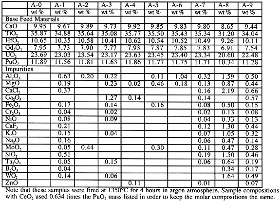
Note that these samples were fired at 1350° C for 4 hours in argon atmosphere. Sample compositions with CeO2 used 0.634 times the PuO2 mass listed in order to keep the molar compositions the same.
Sample preparation and characterization work was shared among the various participating sites. Samples A-1 to A-6 were generally prepared only at one site, whereas samples A-0, A-7, A-8, and A-9 were prepared at two or three different sites. At least one Ce-sample and one Pu-sample of each composition was successfully prepared. All of the Ce-samples and most of the Pu-samples have since been characterized to determine the product phase assemblages. All of the samples reacted well and formed pyrochlore as the dominant phase, even sample A-8 which had 13 wt % impurities in the product. Several trends were observed. Si could not be incorporated significantly into any of the primary ceramic phases. SiO2 forms a separate glassy phase that contains significant amounts of Ca, Al, Ti, and other impurities but little or no Pu or U. The same effect seems to be observed for P. P2O5 was not intentionally added to the form, but was found to be present at about 200 ppm in the TiO2 feed material. P2O5 forms a separate phase that is rich in Ca and P. In general, all other impurities were either vaporized or accommodated into at least one of the primary ceramic phases. Compositions that were low in impurities were for the most part rich in brannerite and lean in zirconolite, and compositions that were rich in impurities were for the most part lean in brannerite and rich in zirconolite. As mentioned earlier, the impurities seem to enhance the reaction kinetics considerably. Compositions with the highest impurity levels had the least amount of actinide oxide in the product, as low as 0.04 vol %, and compositions with the lowest impurity levels had the greatest amount of actinide oxide in the product, as high as 0.6 vol %. Based on image analysis of the SEM images obtained, the compositional range observed in the suite of impurities tests was as follows: pyrochlore-62 to 90 vol %, brannerite-0 to 22 vol %, zirconolite-0 to 25 vol %, rutile-0 to 16 vol %, actinide oxide-0.004 to 0.6 vol %, and silicate glass-0 to 6 vol %.
Many of the Ce-samples were analyzed by electron microprobe analysis. These data were used to generate the preliminary partitioning coefficients given in Table III. As is readily seen, the more common impurities partition preferentially into zirconolite, namely Al, Cr, Fe, Ga, and Mg. A few impurities partition preferentially into the pyrochlore phase, namely Mo, Ta, and W. Ni does not partition significantly. Na, K, and Zn tend to vaporize and/or partition into the silica-rich glassy phase, but the little that remains in the primary phases does seem to partition selectively. Some data are also given for the relative partitioning of impurites into brannerite relative to pyrochlore. With the possible exception of Ni and Zn, the impurities do not seem to partition significantly into the brannerite phase.
Table III. Approximate Partitioning Coefficients for Various Impurities
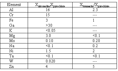
The partitioning coefficient is given as the mole fraction of the element in the phase of interest divided by the mole fraction of the element in the pyrochlore phase
Stability with Respect to the DWPF Pour
Tests in this area fell into two basic areas, evaluation of potential mineralogical and compositional changes during the heating and the slow cool-down, and evaluation of potential cracking during the rapid heat-up.
The heating and slow cool down process was simulated by heating the product forms to between 1000 and 1200° C and cooling at between 1 and 2° C per minute. In every case, no mineralogical change was observed. Phase compositions before and after thermal treatment were analyzed by electron microprobe or quantitative EDS analysis. In every case, there was little or no compositional change. Any small compositional changes observed were well within the statistical variations expected. Compositions before and after one of the thermal treatment tests are given in Table IV. In this particular test, the previously mentioned zirconolite-rich samples were used. These were the samples with the final firing temperature of 1350° C. One of the two samples was then subjected to a simulated DWPF thermal heating and cooling cycle: heat to 1000° C, hold for 15 minutes, cool to 500° C at 2° C per minute, then cool to ambient at 1° C per minute or slower. There were five phases in the sample: zirconolite, pyrochlore, rutile, hollandite, and "reacted" PuO2. Only the compositions for the Pu-bearing phases are given in Table IV. Under the column of DWPF, a "no" means that the data are from the sample that was not subjected to the simulated DWPF thermal cycle and a "yes" means that the data are from the sample that was subjected to the simulated DWPF thermal cycle. Note that the compositional analyses are surprisingly close, even for the "reacted" PuO2.
Table IV. Effect of DWPF Heating and Cooling Cycle on Mineralogical Composition
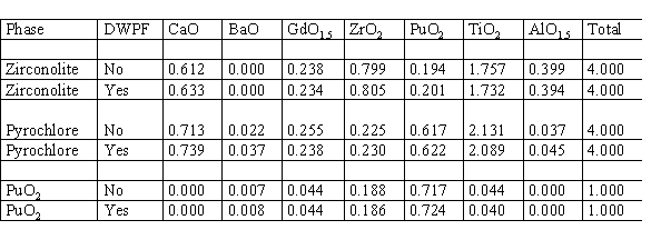
Compositions determined by electron microprobe analysis.
A test was also performed in which molten DWPF-type glass was heated to about 1100° C and then was poured directly onto bare non-radioactive ceramic pellets to determine qualitatively how badly the ceramic would crack due to the thermal shock. In short, the cracking was minimal. Out of 7 pellets, ranging from 2.5 to 4 cm in diameter, only one pellet cracked into two separate pieces. All the other pellets remained intact, with little or no observed cracking.
DISCUSSION
From the above tests, a wide range of equilibrium or near equilibrium compositional data were generated. These data have been combined to form a preliminary processing regime that defines the compositional space in which "acceptable" product is generated. Acceptable is rather arbitrary at this point in the program. Until more durability information is available, an "acceptable" product is defined as containing greater than 50 mol % pyrochlore and up to 50 mol % of brannerite and/or zirconolite. Rutile is up to 20 mol % and other "acceptable" phases total less than 10 mol%. The product must also contain an adequate amount of neutron absorbers, which is presently defined as an overall molar ratio of Hf-to-Pu and Gd-to-Pu that both are equal to or greater than unity. To depict the processing regime as a ternary phase diagram (See Figure 2), the number of degrees of freedom had to be reduced from 6 (the number of oxide components) to 3. Since UO2 and PuO2 are known to be interchangeable in the formulation without changing the compositional phase boundaries, they can be considered as one oxide (AnO2), thus reducing the number of degrees of freedom to 5. The form is designed to contain excess rutile, which is essentially pure TiO2, so its activity is fixed at unity, thus reducing the number of degrees of freedom to 4. Gd is known to partition relatively evenly between the three main phases, pyrochlore, zirconolite, and brannerite. Consequently, the Gd can be factored out without inducing too much error, thus reducing the degrees of freedom to the desired number of 3. The resulting ternary phase diagram is depicted in Figure 2. Perovskite is abbreviated as "Pe." Pyrochlore is abbreviated as "Py." Zirconolite is abbreviated as "Z." Brannerite is abbreviated as "B," and HfTiO4 is abbreviated as "Hf." The "acceptable" processing regime is identified by the diagonal lined region in Figure 2. In the process planned for actual disposition, UO2 and PuO2 will be added to a preblended mixture of the other components. The composition of the preblended mixture would fall at approximately 0.25 units of HfO2 and 0.75 units of CaO. Addition of UO2 and/or PuO2 would fall on a straight line between this point and the AnO2 point. The intersection of this imaginary line with the identified "acceptable"processing range indicates that there is a fairly wide range of UO2 and/or PuO2 compositions that lie within the "acceptable" range.
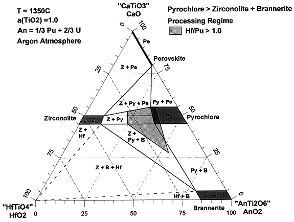
Figure 2. Depiction of the processing regime.
From the data on impurity effects it is possible to generate a preliminary set of feed impurity specifications. It was learned that most impurities fell into one of four categories: (1) volatiles, (2) zirconolite stabilizers, (3) pyrochlore stabilizers, and (4) glass formers. The preliminary specification limits are given in Table V. The limits given are all based on impurity sample A-9 (5.1 wt % impurities in the product) except for the limit on pyrochlore stabilizers, which is based on sample A-8 (13 wt % impurities in the product). The limits are reported in total moles per mole of PuO2. Molar ratio is used rather than weight ratio since the impurities substitute into the ceramic form on an atomic basis and not on a weight basis. It is expected with further testing that the draft limits given in Table V can be relaxed considerably.
Table V. Preliminary Specification Limits on Feed Impurities

The ceramic formulation work currently supports and will continue to support for the foreseeable future a number of task areas in the overall Pu immobilization program, but the primary task in this area for about the next two years is to develop an accurate control model. The complete control model will relate input compositions and processing conditions to how the immobilized form will behave in a repository. It is anticipated that the behavior in the repository will be related primarily to the phase abundances and phase compositions in the immobilized form. Consequently, the portion of the model developed in the ceramic formulation work need only relate input compositions and processing conditions to phase abundances and compositions of the product form. The need for a control model is reinforced by the precedent set by the DWPF HLW vitrification process at SRS. It is anticipated that the control model will be more complicated for the ceramic form than for the competing glass Pu immobilization form. This was the one area in which the competing glass form clearly had an advantage over the ceramic form. Even though the model is expected to be more complicated for the ceramic form than for the glass form, the ceramic forms lends itself readily to non-destructive evaluation (NDE) which can be used to determine or confirm the desired product properties, thus reducing the degree of accuracy required by the control model. The currently planned NDE operations are quantitative X-ray diffraction analysis to determine mineralogical phase abundances and X-ray fluorescence (XRF), probably self-induced, to determine the overall composition. Both the XRD and XRF data in combination with a knowledge of the phase equilibria and impurity partitioning coefficients will then be used to determine the compositions of the individual phases.
CONCLUSION
In conclusion, the ceramic form has been shown to meet or exceed several of the desirable characteristics in a Pu immobilization form: ability to incorporate "high-fired" plutonium oxide of a particle size greater than about 10 micrometers; sufficient compositional flexibility to incorporate significant concentrations of plutonium and neutron absorbers as well as varying impurities in the feed streams; and thermal stability during the glass pouring operation for the can-in-canister configuration. These were items (2), (3), and (4) from the desirable characteristics list. In supporting work, the ceramic form was also shown to meet or exceed all of the other desirable characteristics that were mentioned. Thus, the pyrochlore-based ceramic form is well suited for the mission for which it has been selected.
RERERENCES
BACK