STABILISATION OF URANIUM AND THORIUM METAL SCRAP
A Ridal, A J Brownscombe and B O Hudson
Australian Nuclear Science and Technology Organisation (ANSTO)
PMB 1, Menai, NSW, 2234, Australia
ABSTRACT
After considering various options, controlled calcination has been chosen for the stabilisation of uranium and thorium scrap at ANSTO. A plant based on a rotary calciner has been commissioned and 3,500 kg of uranium scrap and 145 kg of thorium scrap have been stabilised. The reasons for choosing calcination are discussed. The design and operational features of the plant are presented and experience to date is summarised.
INTRODUCTION
Fabrication and machining of uranium and thorium metals generate scrap waste. Such waste is common in the nuclear industry. At the Australian Nuclear Science and Technology Organisation (ANSTO), approximately 4 tonnes of thorium and natural and depleted uranium scrap have accumulated over the past 35 years. The scrap exists in the form of sawdust (i.e. finely divided particles), swarf (i.e. machine turnings), and thin and thick melting and casting remnants. In these forms, both uranium and thorium tend to be pyrophoric; consequently the scrap has been stored in 200 drums (each 20 litre capacity) under kerosene or, in some cases, oil. As a safety measure and as a pre-requisite for longer-term storage or disposal, the scrap waste needed to be stabilised.
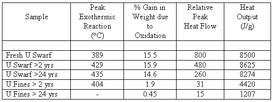
As the majority of both uranium and thorium scrap had been in storage for over 25 years, a preliminary investigation was performed to determine whether any oxidation had occurred (i.e. whether its flammability had changed) during the storage period. Samples of both swarf and fines were taken from depleted uranium scrap which had been in storage for > 24 years and > 2 years, respectively, together with a sample of freshly-machined uranium. Each sample (~20 mg) was subjected to thermal gravimetric analysis (TGA) in flowing air heated at 5oC/min to a maximum of 600oC. Changes in weight and heat-flow were recorded. The results are summarised in Table I.
Table I. Summary of Uranium TGA Results

For the swarf, the weight gain and total heat generated are comparable for all samples but the magnitude of the peak heat-flow decreases with increasing storage period; this indicates that the reaction-rate is slower for the older material. On the other hand, the fines show little weight gain and low heat-flow, suggesting that the fines have been largely oxidised.
STABILISATION OPTIONS CONSIDERED
The following options for the management of the scrap were examined: recovery by melting, alloying with aluminium, wet chemical oxidation, conversion to a stable oxide by burning and controlled calcination.
Recovery by Melting
The recovery of thorium, depleted and natural uranium as monolithic blocks could not be justified economically. Moreover, the recovery rate, particularly from the oxidised fines, was questionable [1]. Nevertheless, a trial was undertaken on melting ~70 kg of pre-compacted new swarf in a graphite crucible under an argon atmosphere (using 10 wt% calcium chloride as a flux). The results were not encouraging with melting occurring in only the outer regions. Disadvantages also included the fire risk from friction during compaction.
Alloying With Aluminium
The solubility of uranium in molten aluminium varies from 9 wt% at 650oC to 22 wt% at 800oC [2]. In the laboratory trial, aluminium was melted at 660oC, cast on top of 40 g uranium swarf and the mixture reheated to 800oC for 1 hour. A sample taken for XRD analysis indicated no uranium in the aluminium matrix.
Other disadvantages included its applicability to only fresh-machined swarf and the 4:1 aluminium-to-uranium ratio.
Wet Chemical Oxidation
Los Alamos National Laboratory has developed a chemical process to oxidise uranium swarf [3]. The process consists of draining-off storage oils, treating with sodium hypochlorite to wet oxidise the uranium to uranyl hydroxide which is then converted to uranium dioxide using sodium thiosulphate. The resulting filter-cake can be immobilised in a cement matrix.
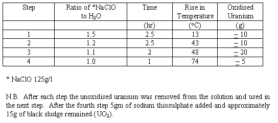
A trial was conducted on 60 g of depleted uranium swarf at ANSTO. The results are summarised in Table II.
Table II. Summary of Chemical Oxidation Trial

The results indicate that the reaction proceeded smoothly and to completion. The slurry was filtered and chemical analysis of the filtrate showed a very low uranium content (1.5 m g/litre).
In addition, a trial was also conducted on a small sample (10 g) of thorium swarf. The reaction-rate was found to be very slow (at least 10 times slower than uranium) but the reaction appeared to go to completion.
Further trials and development would be required before this process could be implemented for all the scrap waste, particularly thorium. The process was judged as being too complex for the relatively small amount of waste at ANSTO. The generation of a liquid waste stream was also a disadvantage. It was noted that a high-temperature step would be needed to dry the filter-cake.
Burning
Over the years, there have been a number of attempts to stabilise uranium swarf at ANSTO by burning within appropriately designed furnaces. Throughput was generally low (typically ~ 5 kg per 24 hours) and problems have been encountered with filter blockages, and the handling and washing of the swarf prior to burning.
Calcination
The TGA analyses of uranium samples (Table I and Fig 1) indicated that uranium swarf could be oxidised by calcination at 400-450oC using a controlled atmosphere. Subsequent laboratory experiments using a rotary calciner with progressively larger amounts of depleted uranium (100 g up to 2 kg) successfully oxidised the uranium to U3O8 as confirmed by XRD analysis. Fig 2 shows how exothermic reactions were effectively controlled by reducing the air-flow.
TGA analyses for thorium swarf indicated two exothermic peaks at ~490oC and ~940oC (Fig 3). Calcination of 100 g sample of thorium swarf confirmed that complete oxidation to ThO2 could be achieved at 900oC.

Figure 1. Thermal Analysis of Uranium

Figure 2. Controlling Uranium Exothermic Reaction by Reducing Air Flow

Figure 3. Thermal Analysis of Thorium
CONTROLLED CALCINATION
Controlled calcination was selected as the preferred option because of its relatively high throughput, its relative simplicity, its ability to deal with both uranium and thorium scrap, and the availability of suitable equipment at ANSTO. A 'rotary' calciner was preferred to ensure that the material exposed to the oxidising environment was continually changing. The rotary calciner and its ancillary equipment were designed, built and commissioned in late 1996. Routine operation began January 1997.
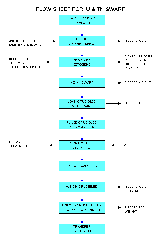
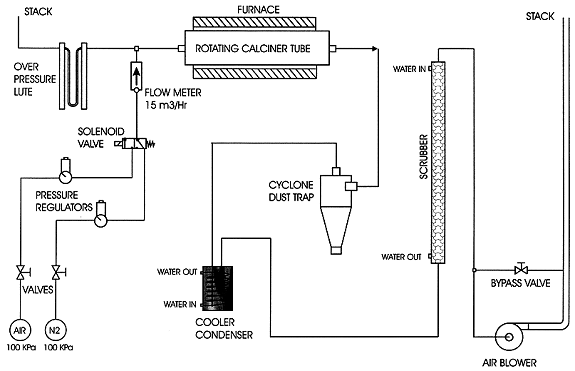
The process flowsheet is shown in Fig 4 and a schematic of the plant is given in Fig 5. The basic process steps are as follows.

Figure 4. Flow Diagram for U & Th Swarf Calcination

Figure 5. Schematic of Controlled Calcination Process
The swarf is drained overnight under a nitrogen atmosphere in a drum with a steel screen base. The drained swarf is loaded into three stainless-steel tubular crucibles (up to 10 kg per crucible) through a 10 cm diameter opening at the end of each crucible. After loading, a stainless-steel disc is attached to restrict the opening to 2.5 cm diameter through which a gas-tube passes. The crucibles are transferred via a mobile glove-box into the calciner. The gas-tube, centred through the three crucibles, permits nitrogen and air to be injected into the swarf. Thermocouples monitor the temperature in each crucible. The furnace temperature is set initially at 200oC and nitrogen gas is used to flush any residual kerosene vapours from the system. The furnace temperature is then increased to 500oC for uranium, and 900oC for thorium. Once oxidation is substantially completed (indicated by decreasing thermocouple temperatures), the furnace is held at temperature for a further 3 hours to ensure complete stabilisation.
After cooling, the crucibles are emptied through a screen-sieve into plastic bags via the mobile glove-box. The plastic bags are sealed, weighed and placed into 20 litre drums for storage. The weight increase and colour of the resulting oxide powder are qualitative guides as to whether complete oxidation has been achieved; quantitative confirmation is provided by XRD analysis.
Oxidation is controlled by automatically shutting-off the air-flow and flooding with nitrogen if any crucible temperature exceeds 900oC for uranium (or 1050oC for thorium). When the temperature subsequently falls to 600oC for uranium (or 900oC for thorium), the nitrogen-flow is automatically shut-off and the air-flow is restarted.
The off-gas from the calciner passes through a cyclone to remove entrained particles and through a cooler-condenser to remove residual kerosene. It then passes through a water-scrubber to remove fine residual particles prior to being vented from the building via a stack. A separate ventilation system is used for the mobile glove-box and for the initial swarf drainage operation, and is exhausted from the building via a pre-filter and absolute filter. The stacks are continuously monitored for entrained uranium and after 12 months operation no contamination has been measured.
OPERATION EXPERIENCE
Initially, priority was given to calcining the recently-generated swarf because of its greater potential to spontaneously ignite. During commissioning, a spontaneous fire occurred whilst draining the kerosene from the swarf overnight, however, only minor damage resulted. Subsequent drainage operations were performed under a nitrogen gas blanket. A second incident occurred after fresh uranium turnings had temporarily been stored in water instead of kerosene. After draining, this swarf was very dry, and friction during crucible-loading caused ignition. It was then decided that only kerosene would be used for storage of swarf and that freshly generated swarf would be allowed to age before calcination. Thus the old swarf is being calcined first. No further fires have occurred in 139 operations.
As outlined above, calcination was controlled by changing the calciner atmosphere from air to nitrogen when the swarf temperature exceeded a preset threshold. From experience, it has been found that calcination can also be controlled by reducing the air-flow and by starting oxidation at a lower temperature of 300oC for uranium and 400oC for thorium. With the incorporation of these two methods, the oxidation temperature for uranium and thorium rarely exceeds 900oC.
The thorium metal scrap was stabilised in 6 operations involving 145 kg of scrap. The operation was successful, with added caution in handling the thorium material due to its relatively high activity 500 m Sv in contact with the side of the drum and 100 m Sv on the base, compared with 20 m Sv from the uranium drums. The operators were closely monitored during this operation with the highest dosage being 0.16 mSv. The operators have averaged ~ 2 mSv during the whole year operation.
The overall performance of the plant has been most satisfactory. All uranium and thorium scrap in storage has been stabilised in 139 calciner operations, with a total of 3500 kg of depleted and natural uranium and 145 kg of thorium having been calcined. In summary, calcination has proved to be a simple cost effective technique for stabilising small to moderate amounts of U and Th scrap waste.
ACKNOWLEDGMENTS
The authors wish to acknowledge the services of Mr J Chapman for his assistance in the design and construction of the electronic gas system, Mr D Cassidy for TGA analysis, Dr E R Vance for the XRD results and finally the Health and Safety Division for monitoring the process.
REFERENCES