REMOTE LASER PROCESSING OF RADIOACTIVE
COMPONENTS AT THE ENERGY TECHNOLOGY
ENGINEERING CENTER (ETEC)
S. N. Shah, R. B. Hardy, and D. W. Kneff
The Boeing Company
Rocketdyne Propulsion & Power
ABSTRACT
A demonstration test was performed to evaluate the applicability of remote laser cutting to decontamination and decommissioning activities using off-the-shelf hardware. A Nd:YAG laser was employed at an output power of 0.8 kW to size-reduce approximately 300 radiologically contaminated nuclear fuel storage tubes at the Energy Technology Engineering Center. The cutting was performed remotely in a containment tent, with the laser located outside the containment area and the laser beam transported to the cutting site using a fiberoptic delivery system. Preliminary tests were performed at an outside laboratory prior to the ETEC demonstration to establish a data base of laser cutting parameters, and knowledge gained from the successful demonstration was transferred to a commercial firm for follow-on laser cutting deployment tests.
INTRODUCTION
Near-term dismantlement activities are required for a large number of nuclear reactor and processing facilities in both the DOE complex and the commercial sector. These activities include component size reduction, contaminant characterization, and decontamination. They provide major challenges where innovative approaches using state-of-the-art technologies can significantly reduce operating costs and personnel exposures. The Energy Technology Engineering Center (ETEC) has been investigating the suitability of lasers for remote dismantlement applications. An initial study concluded that the capability of lasers with fiberoptic beam delivery systems to perform remote thermal cutting makes them an attractive tool for decontamination and decommissioning (D&D) applications in hazardous environments.(1)
The earlier ETEC study considered several different laser types and compared their cutting capabilities (including cutting rates, cut width, and secondary waste generation) with current-practice technologies, of which plasma-arc cutting is the baseline. Two laser systems were identified as promising candidates for remote laser cutting D&D applications: Nd:YAG (neodymium-doped yttrium aluminum garnet) and the Chemical Oxygen Iodine Laser (COIL). Both lasers generate beams whose wavelengths transmit through optical fibers with minimum power loss for remote beam delivery. Nd:YAG is available commercially for "off-the-shelf" use, while COIL has long-term potential for applications requiring a much higher laser output power.
ETEC has followed up this study with a laser cutting deployment demonstration using contaminated components in a radiologically controlled facility. The objective was to demonstrate the ability of a currently available, off-the-shelf Nd:YAG laser system to size-reduce a large number of components remotely for characterization and disposal. The demonstration task included four primary elements: (1) perform laboratory bench-scale tests to establish cutting parameters; (2) design and fabricate a fixture for remotely handling contaminated components and the laser focusing head during cutting; (3) remotely size reduce approximately 300 contaminated fuel storage tubes; and (4) transfer the technology gained from the laser cutting tasks to a commercial firm for an enhanced follow-on demonstration program. This paper describes the ETEC demonstration tests and summarizes the information gained from the program.
LABORATORY LASER CUTTING TESTS
Nd:YAG laser systems are available off-the-shelf with laser power levels of up to about 4 kW. Lumonics Ltd. provided the use of a 2-kW laser for use both in the ETEC deployment and in the follow-on commercial tests, performed by the Manufacturing Sciences Corporation (MSC) of Oak Ridge, TN. The first step in preparing for the on-site deployment tests was to establish the initial laser operating parameters to be used, and to demonstrate the capability of the laser system to perform the required cutting. The parameters of interest included laser power level, material thickness, cutting speed, cutting head focal length, stand-off distance, assist gas type, and assist gas pressure. The use of a Nd:YAG laser for cutting requires an "assist" gas flow across the cutting region. This assist gas supplies energy required to perform the cutting and blows the debris created by the cutting process away from the cutting zone.
Initial laboratory tests were performed at the Edison Welding Institute on the Ohio State University campus using a continuous-wave (non-pulsed) 3-kW Nd:YAG laser at power levels of 1000 to 2700 Watts.(2) The emphasis in those tests was on cutting metals that are considerably thicker than the materials used in the ETEC tests, in order to provide data for a greater range of applications. The baseline material was 1-cm-thick steel pipe, which is comparable to the material thicknesses addressed in the follow-on MSC demonstration tests. The laser beam was delivered to the workpiece using a 15-m-long fiberoptic cable with a 0.6-mm-diameter fused silica core. Total power loss associated with this system was about 12%, which includes 4% in the laser beam injection and focusing optics, and 8% in the fiberoptic beam delivery system.
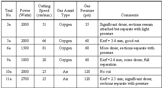
A total of forty-one test cuts were made, using two different focusing end effectors (F4 and F8), two different assist gases (oxygen and air over a range of gas pressures), and cutting speeds ranging from 25 to 81 cm/min. The F4 end effector (where F is the beam focal length divided by the beam diameter at the focusing optics) produces a smaller spot size, while the F8 end effector has a longer depth of field, allowing greater tolerance in positioning the laser cutting head.
Selected laboratory test results for the F8 optics are summarized in Table I. The assist gas type and pressure were found to be the primary parameters controlling the quality of the cuts for both end effectors, with the reaction between oxygen and the workpiece producing most of the energy needed to melt the steel. An air assist gas did not produce acceptable cuts. Oxygen worked well, but oxygen gas pressures that were either too low or too high produced excessive dross on the backside of the workpiece. The kerf (cut) width, which affects secondary waste generation, was narrower for the F4 optics and for faster cutting speeds or lower laser powers. The focal position could be varied ±3 mm with little effect on the quality or speed of the cut. The results of the laboratory tests led to the selection of oxygen as the assist gas and an F6 focusing head, the latter to provide a larger depth of field and wider kerf than the F4 optics. The larger depth of field provides greater tolerance in the focusing head standoff distance from the workpiece, and the wider kerf helps keep molten dross from bridging the cut and rewelding it.
Table I. Selected Results from Initial Laboratory Tests to Determine Key Laser
Cutting Parameters for 1-cm-thick Steel

ETEC DEMONSTRATION TEST SETUP
The objective of the ETEC laser deployment demonstration was to use an off-the-shelf Nd:YAG laser system to section approximately 300 radiologically contaminated nuclear fuel storage tubes for inspection and disposal. The cuts were to be performed remotely, using fiber optics to deliver the beam to a radiologically controlled tube cutting site within a containment tent. Each 3-m-long, 12.7-cm-diameter, 16-gauge (1.6-mm-thick) steel tube was to be split open and sectioned into four approximately equal half-cylinder sections to reduce disposal volume and to provide access to the tube interiors for inspection and possible decontamination.
The general configuration used for the ETEC deployment tests is shown schematically in Fig. 1. The laser resonator, power supply, water chiller, gas assist supply, and operational controls were located in a nonhazardous environment for protection and maintenance accessibility. The laser focusing head and a tube holding fixture were located within the containment tent. The tent was fitted with a HEPA-filtered ventilation system, a viewing window constructed of laser-wavelength (1064 nm) absorbing material, and an interlocked door that shut off the laser if opened. Since the effective cutting distance was only a few millimeters, the primary laser hazard within the tent was potential eye exposure to a reflected laser beam. The beam was delivered to the cutting site within the containment tent using a 15-m-long, 1-mm-diameter-core fiberoptic cable. The cable was terminated at an F6 laser focusing head, which was mounted on the tube holding fixture. Oxygen assist gas was transported from a gas source/regulator outside the tent to the cutting site through a long tube that was attached to the laser focusing head. The laser was an off-the-shelf Lumonics 2-kW Nd:YAG laser, operating in a continuous-wave mode.

Figure 1. Schematic Diagram of the Laser Cutting Configuration for the ETEC Tests.
The cutting process was automated by controlling tube and laser focusing head movements on the tube holding fixture (Fig. 2). The fixture was designed by ETEC and fabricated from off-the-shelf catalog items. Each tube was placed horizontally on the fixture bed, which positioned the tube outer wall about 5 mm from the tip of the laser focusing head. Cutting was performed by translating the focusing head, with its assist gas delivery system, along the length of the tube for longitudinal cuts, and rotating the tube for circumferential cuts. These motions were controlled by a remotely operated console with the operator monitoring the process through the tent viewing window. For each tube, the laser was started at one tube end and the cutting head was moved linearly along the tube length to the tube’s halfway point, making a longitudinal cut through the closest tube wall. At that point, the linear motion was stopped and the tube rotated 360o about its long axis to produce a circumferential cut that segmented the tube into two pieces. The laser cutting head linear motion was then resumed to continue the longitudinal cut to the far end of the tube. The tube was then rotated another 180o to place the opposite side of the tube wall in front of the cutting head, and the laser head linear travel direction was reversed to make a second cut along the length of the tube that completed its longitudinal sectioning. The loading of the tubes and the unloading of the cut sections were performed manually, as only the laser cutting was automated for this demonstration.

Figure 2. Remote Tube Handling Fixture with Mounted Laser Focusing Head.
LASER CUTTING DEMONSTRATION TESTS
Several initial cutting tests were performed with clean mock-up tubes to establish laser system operating parameters. Those tests showed that good cutting performance could be achieved using a laser power level of 0.8 kW, an oxygen assist gas pressure of about 70 psi, and a standoff distance between the tip of the focusing head and the cutting surface of about 5 mm. The optimum linear cutting speed established for the tube cutting was about 400 cm/minute. This produced a clean cut with little dross and a kerf width of about 0.9 mm. The cutting speed could be increased significantly by using higher laser power levels and utilizing an auto-focusing cutting head for finer control of the standoff distance. However, the additional cost of an auto-focusing head was not justified for this demonstration because of the uniformity of the tubes to be cut.
These optimized cutting parameters were then utilized to segment the large inventory of contaminated storage tubes. The laser cutting operation is shown in Fig. 3. Each of the contaminated tubes was sectioned in about 2˝ minutes, including the time required to load the tube on the fixture and unload the cut sections. For this operation, the laser cutting was controlled from outside the containment tent and a radiation-trained worker was stationed in the tent to perform the material handling operations. The inside worker was attired in personal protective equipment, including a filter mask and laser goggles. Significant vapor was generated by the cutting process, and dictated routine replacement of the tent’s pre-filters and bag filters. The laser system worked well, and filter replacement became the primary maintenance requirement during the tube cutting operations. The entire inventory of fuel storage tubes from the ETEC storage vault was successfully size-reduced for disposal within a 2-week period.

Figure 3. Laser Cutting of a Fuel Storage Tube, Showing the Cutting Operation and the Laser Focusing Head.
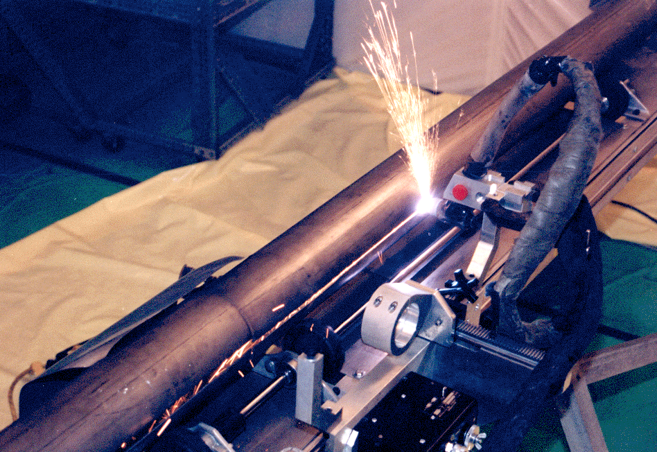
Following the laser cutting operations, a number of cutting tests were performed using a plasma-arc torch and clean mock-up tubes to provide comparative data using current-practice technologies. These tests used the same tube holding fixture, remote operation, and cutting procedures as used for the laser cutting; one of the plasma-arc cutting tests is shown in Fig. 4. Results of the plasma-arc tests showed that the optimum linear cutting speed was about the same as for the laser cutting, but the kerf width was about 2˝ times larger (2.2 mm). Plasma-arc cutting thus generated a proportionately larger quantity of secondary waste that included more airborne particulate and required more frequent air filter changes. Extensive ETEC experience with plasma-arc torches in D&D applications has also shown that such torches require much more frequent maintenance when used in extended applications. That was not demonstrated in these tests because of the limited plasma-arc use.

Figure 4. Plasma-Arc Cutting of a Mock-Up Fuel Storage Tube, Using the Same Fixture and Identical Cutting Procedures as Used in the Laser Cutting Demonstration.
LASER CUTTING EVALUATION FOR D&D APPLICATIONS
The laser cutting tests successfully demonstrated the use of an off-the-shelf laser system to segment a large inventory of contaminated storage tubes for inspection and disposal. The laser system could be located outside of the hazardous materials handling and cutting environment, simplifying maintenance and precluding contamination of the more costly system components. The latter greatly improves transportability of the system from site to site and thus offsets the relatively high initial capital cost of the system. Preliminary laboratory tests demonstrated that this same laser system can be used to cut much thicker materials. Further, the laser cutting speed for the ETEC tubes could have been increased significantly by using a higher laser power and an auto-focusing cutting head, coupled with some modifications to the tube holding fixture.
Comparisons between the laser cutting and plasma-arc cutting results showed that the two technologies could be employed at comparable cutting speeds, but the plasma-arc system generated a much larger quantity of secondary waste. That difference, plus the higher maintenance requirements for plasma-arc hardware, results in higher cutting costs for the plasma-arc system. For example, filter change-out is required 2˝ times as often for plasma-arc cutting, and plasma head change-out is required about 40 times as often as replacement of the laser focusing head’s front disposable cone. This translates to higher personnel exposures (more frequent and longer hazardous environment entries) and greater waste generation (filters, personal protective equipment) for plasma-arc cutting.
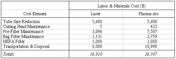
The ETEC demonstration was a relatively small-scale application intended to show the capabilities of a remote laser cutting system, and no cost benefits were expected. However, a cost comparison was made between the two technologies for size-reducing the ETEC storage tubes, including labor, material disposal, and material costs for filters, personal protective equipment, and replaceable hardware components. The results of that comparison are summarized in Table II, and show about a 33% cost savings by using laser cutting. This does not include the cost of developing the tube handling fixture, or the laser versus plasma-arc torch capital equipment costs. The significance of those costs is highly dependent upon the size of the D&D project.
Table II. Cost Comparison Between Remote Laser and Plasma-Arc Size-Reduction
of the ETEC Storage Tubes

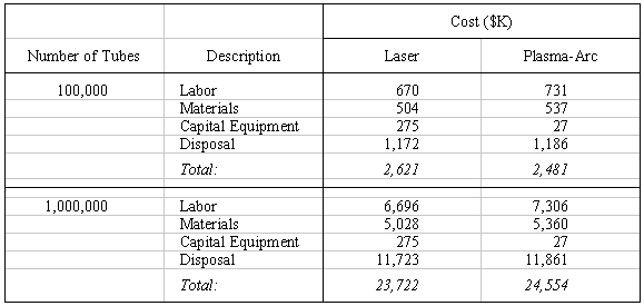
Cost comparisons were also made for the size-reduction of significantly larger quantities of contaminated tubes. Here the pre-filters and bag filters, which represented a significant cost factor for the ETEC operation, were replaced by self-cleaning pre-filters. These comparisons included the capital equipment costs of the cutting hardware, which are significantly higher for laser cutting. Sample summary results are presented in Table III. They indicate that plasma-arc cutting is less expensive for smaller quantities of tubing (because of capital equipment costs), and laser cutting is less expensive for larger quantities. The break-even point in these comparisons was at about 230,000 tubes.
Table III. Cost Comparison Between Remote Laser and Plasma-Arc Size-Reduction
of Large Quantities of Contaminated Tubes

CONCLUSIONS AND TECHNOLOGY TRANSFER
The overall conclusion from the ETEC site deployment demonstration tests is that current, off-the-shelf laser technology with fiberoptic remote beam delivery can be used effectively for component size-reduction activities in D&D applications. It offers attractive opportunities today for both cost and personnel exposure reduction, and the opportunities will expand greatly with near-term advances in commercial laser development.
The successful ETEC results justify further deployment of the laser cutting system. The laser used in these tests was subsequently transferred to the Manufacturing Sciences Corporation (MSC), a commercial facility in Oak Ridge, TN, for follow-on deployment tests. At MSC, the laser system was automated further and utilized to size-reduce 1.27-cm-thick converter shells from the Oak Ridge K-25 plant. Experience and lessons learned from the ETEC tests were used to provide technology transfer and technical support for that application.
ACKNOWLEDGMENTS
The authors wish to thank T. Kugler and C. Ankerson of Lumonics, Ltd. for the loan of the Nd:YAG laser system and the chiller for the demonstration activities. They also acknowledge the programmatic and funding support from J. M. Hyde (DOE-HQ), K. Abbott (DOE-OAK), and M. E. Lee (ETEC), and the technical support of M. A. Spenard, P. H. Waite, R. A. Marshall, R. I. Brownell, D. W. Hickman, R. G. Palmer, Jr., and K. Darcy (ETEC).
REFERENCES