DEMONSTRATION OF IN-SITU STABILIZATION OF BURIED
WASTE AT PIT G-11 AT THE BROOKHAVEN NATIONAL
LABORATORY GLASS PITS DISPOSAL SITE
J. Heiser, B. Dwyer and J. Gilbert
Brookhaven National Laboratory
Upton, NY 11973
ABSTRACT
In 1989 BNL was added to the EPA’s National Priorities List. The site is divided into seven operable units (OU). OU I includes the former landfill area. The field task site is noted as the AOC 2C Glass Holes location. Beginning in the 1960's and continuing into the 1980's, BNL disposed of laboratory waste (glassware, chemicals and animal carcasses) in numerous shallow pits. The drivers for remediating the pits are; historical records that indicate hazardous materials may have been disposed of in the pits; ground water contamination down gradient of the pits; a test excavation of one of the glass holes that unearthed laboratory glass bottles with unidentified liquids still contained; and the fact that BNL rests atop an EPA designated sole-source aquifer.
The specific site chosen for this demonstration was pit G-11. The requirements that lead to choosing this pit were; a well characterized pit and a relatively isolated pit where our construction operations would not impact on adjacent pits. The glass holes area, including pit G-11, was comprehensively surveyed using a suite of geophysical techniques (e.g., EM-31, EM-61, GPR). Prior to stabilizing the waste form a subsurface barrier was constructed to contain the entire waste pit. The pit contents were then stabilized using a cement grout applied via jet grouting. The stabilization was performed to make removal of the waste from the pit easier and safer in terms of worker exposure. The grouting process would mix and masticate the waste and grout and form a single monolithic waste form. This large monolith would then be subdivided into smaller 4 foot by 4foot by 10-12 foot block using a demolition grout. The smaller blocks would then be easily removed from the site and disposed of in a CERCLA waste site.
During the summer of 1997, the Glass Pits Disposal area remediation was completed. The stabilized waste in pit G-11 were removed and inspection, coring and testing were performed. This paper will discuss the construction, inspection, performance and adequacy of the stabilization process and subsequent subdivision and removal efforts. Data should also be available on the TCLP result of the stabilized monolith.
INTRODUCTION
Contaminated soils and buried waste, treated and untreated, pose a threat through contaminant transport to groundwater or back to the surface. Many hazardous waste sites contains buried waste constituents that, if left untreated, may eventually become mobile in the environment. In many instances this may result in unacceptable human health and environment exposures. One of the options for control of contaminant migration from such buried waste sites is in-situ stabilization of the waste. In addition to preventing spread of contamination (and resultant clean-up costs) such in-situ treatment could result in large cost savings and reduced worker exposure when compared to conventional restoration technologies (e.g., excavation, re-treatment and re-disposal of the waste).
In 1989 Brookhaven National Laboratory (BNL) was added to the EPA’s National Priorities List. The site is divided into seven operable units (OU). OU I includes the former landfill area. The field task site is noted as the AOC 2C Glass Holes location. Beginning in the 1960's and continuing into the 1980's, BNL disposed of laboratory waste (glassware, chemicals and animal carcasses) in numerous shallow pits. In the glass holes area, historical records indicated that there were 10 glass pits excavated, but further investigation revealed the presence of 17 glass pits. The glass pits were typically excavated with a clam-shell. Individual pits were approximately 3.0 to 4.6 meters (10 to 15 feet) in diameter and 3.0 to 4.6 meters (10 to 15 feet) deep. Waste materials and backfill were placed into the individual unlined pits in lifts with final backfill to grade. Record keeping on the number of pits, location and contents were poor by today’s standards. This makes it difficult to fully assess the problem and to develop a remediation plan. The drivers for remediating the pits are; historical records that indicate hazardous materials may have been disposed of in the pits; ground water contamination down gradient of the pits; a test excavation of one of the glass holes that unearthed laboratory glass bottles with unidentified liquids still contained; and the fact that BNL rests atop an EPA designated sole-source aquifer.
The designed remediation called for the excavation and removal of the waste from the pits. At this time interest in in-situ treatment of buried waste was sufficient to allow a demonstration at one of the pits. The final remediation was still removal but such a demonstration would not interfere with the remediation and might enhance the removal by reducing the worker exposure and facilitating removal as a monolithic waste form rather than unconsolidated waste. An isolated pit was chosen for the demonstration. Many of the glass bottles in the pit contained liquids and there was concern that should the stabilization not fully mix the grout and waste then materials might seep into the aquifer. Therefore, the pit was first isolated from the environment by a containment barrier to prevent contamination spread to the shallow aquifer (approximately 3 meters below the pit bottom). The stabilization task was actually a subtask of a demonstration of a close-coupled subsurface barrier technology.[1] The barrier would capture any leakage of hazardous materials should they be mobilized by the solidification efforts. After verifying the competency of the barrier the stabilization of the pit contents proceeded.
SITE
Brookhaven National Laboratory is located in Upton, Long Island, New York, near the geographical center of Suffolk County. Suffolk County contains approximately 1.32 million people. Originally constructed and used by the U.S. Army during World Wars I and II and by the Civilian Conservation Corps between the wars, the site was known as Camp Upton. In 1947, the ownership of the property was transferred to the Atomic Energy Commission for research on atomic energy and materials. In 1975, the site was transferred to the Energy Research and Development Administration, and finally to DOE in 1977. It is a multi-disciplinary scientific research center operated by Associated Universities Inc.
Long Island’s hydro geologic system consists of three major aquifers, the Lloyd Sand Member of the Raritan, the Mongothy Formation, and the upper Pleistocene Glacial deposits separated by two confining units (the Raritan Clay between the Lloyd and the Mongothy aquifers, and the Gardiners Clay unit between the Mongothy and the upper glacial aquifer). Taken together, these aquifers and confining layers have been designated by the EPA as a Sole Source Aquifer System. The Mongothy aquifer is the principle public water supply aquifer beneath Long Island. The Upper Pleistocene Glacial Aquifer is an important aquifer for private and public water supplies.
The specific site chosen for this demonstration was pit G-11 of the glass holes (AOC-2C). The requirements that lead to choosing this pit were; a well characterized pit and a relatively isolated pit where our construction operations would not impact on adjacent pits. The glass holes area, including pit G-11, was comprehensively surveyed using a suite of geophysical techniques (e.g., EM-31, EM-61, GPR).[2] Pit G-11 was originally believed to be a doublet pit consisting of two nearly connected pits. Just prior to this demonstration (but after the pit selection process) the data was re-evaluated using better analysis methods, resulting in the pit being re-defined as a single pit. The layout for grouting the pit was re-set accordingly and the pit outline was staked out by BNL-Office of Environmental Restoration personnel based on this evaluation. In the area of concern the water table is approximately 13 meters (42ft) from the ground surface with a gradient from the north northwest to the south southeast. There is also a 0.3M (1ft) thick cobble layer located approximately 1.5M (5ft) below grade consisting of 2 to 8cm (1 to 3in) quartz stones. Groundwater sampling in the OU-I area has shown the presence of volatile organics, heavy metal(s), and fission product(s). There is some uncertainty as to the exact origin of contaminants within OU-I; for instance, is a specific contaminant from AOC 2A or the Former Landfill and so on.
IN-SITU STABILIZATION OF THE PIT CONTENTS
The pit contents were stabilized with a cement grout via jet grouting. Jet grout construction is performed by injecting a grout through a pipe into subsurface. The pipe has a drill tip on it which is used to drill the initial borehole. The pipe is then rotated 360° while injecting the grout and slowly withdrawn from the ground. The high velocity jet masticates and mixes the soil and grout which results in a column ~1 meter in diameter that resembles a pancake stack. The technique requires a pumpable grout that can be injected at pressures greater than 300 bars (5000 psi) through a small orifice, typically 2mm. The small orifice limits any aggregate additions to fine particle sizes. Most often, the jet grouting uses a low viscosity grout (~5 cps), and incorporates only the existing soils for aggregate.
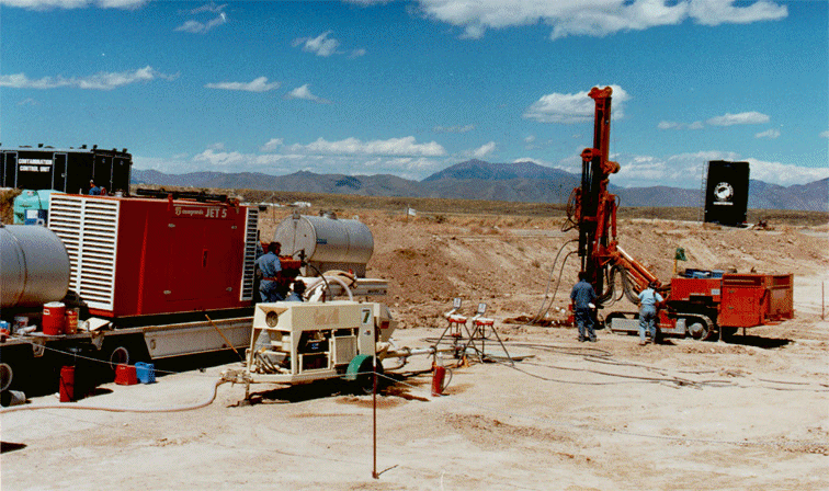
A Casa Grande C-6 jet grouting unit (Figure 1) was mobilized from Hanford to Brookhaven National Laboratory during the last week of May 1996. This included: a diesel/hydraulic crawler-mounted injector, and a diesel high-pressure, triplex slurry pump. On arrival at the glass pit location, all systems were configured for operation, interfaced, and tested for systems performance before initiation of the containment barrier and in-situ stabilization demonstration activities.
Figure 1. Casa Grande Jet Grouting Unit Used for In-situ Stabilization of Pit G-11 at Brookhaven National Laboratory.
Using plastic sheet piling a large cell was constructed around the waste pit, internal to the containment barrier, forming a vertical rectangular wall around the pit contents. This wall served as a "mold" for the in-situ stabilization, to keep the outer edges of the monolith uniform and to prevent the stabilization grout from adhering to the barrier walls. The panels were placed by trenching around the pit to a depth of two meters. Plastic sheet pile sections were assembled in the trench and the trench was then backfilled. The internal area bounded by the sheet piling and containing the waste was then solidified.
In-situ stabilization was performed in June 1996, by Applied Geotechnical Engineering and Construction, Inc (AGEC). Grouting took place over a two day period. The initial parameters chosen to install the cement were based on the Hanford installation. The cement grout was a standard Portland type I mix (w/c=1, by weight) specified by Sandia National Laboratory (SNL) which provided the engineering aspects of this project. The grout was received as a ready mix supplied by a local vendor and trucked to the site in a cement mixer. The cement was delivered to a 210L (55gal) surge tank fitted with a screen to remove coarse particulates that may have been in the ready-mix truck. From the surge tank the cement was transferred via a trash pump to the high pressure pump to be delivered to the drill stem at 400 bars (6000psi). The tractor-mounted drilling unit was positioned at the first hole, the drilling angle set at 90° to the horizon and the drill stem driven into the ground to the desired depth. The orifice was set at 2.2 mm and there were two opposing openings on the drill tip. The cement stream was activated and grouting proceeded as follows. While delivering the grout at 400 bars (6000psi) the drill stem was slowly revolved and withdrawn from the ground. The withdrawal was performed in discrete 5cm steps at a rate of 4.25 seconds per step. Rotation occurred at two revolutions per step. The step rate was adjusted in the field to minimize spoils return. Spoils production was slightly higher than observed at an earlier cold test at Hanford, WA, but still at an acceptable level. This sequence was repeated for each of the odd number holes in the first line of columns and then repeated on the even number holes. Alternating holes was performed to eliminate cross-communication between columns. If the second column injection were to be performed immediately adjacent to the first, because of the overlap in column the high velocity grout would break through to the first grouted area. Any grout injected would/could short circuit into the first hole and be pumped via the drill hole to the surface as spoils rather than completing the second column. Allowing the first column to cure slightly eliminated such cross-communication.
Once the first row of columns was completed a second row inside the first row of columns was grouted behind and touching the first row in a honey comb fashion. Columns were 0.66 to 0.76M (26 to 30in) in diameter and spaced 0.5M (21 in) on centers to allowed for sufficient overlap of adjoining columns and assured complete coverage.
Spiral wound tubing was inserted vertically through the entire height of the grouted monolith such that the array of tubes outlined 1.3M by 1.3M (4ft by 4ft) cells. The tubes were sealed at the bottom and simply pushed into the drill hole following completion of a column. On plan view, the tubing was placed every foot in the east to west direction and every two feet north to south. Figure 2 shows the pit stabilization in plan view. Retrieval picking eyes were also placed in each stabilization cell before the materials cured. Upon complete curing of all cells, final retrieval of solidified monoliths containing the stabilized contaminant materials would be facilitated by vertical crane withdrawal using the picking eyes in each cell. Each cell monolith could then be containerized, transported and stored, disposed to other facilities, or other actions taken in accordance with Brookhaven National Laboratory closure plans.
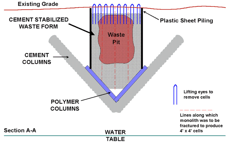
Figure 2. Cross-sectional View of In-situ Stabilization of Waste Pit.
The monolith was allowed to cure for several months. On September 4, 1996 personnel from AGEC returned to BNL to apply the Bristar demolition grout. This is a fast curing expansive grout that is commonly used to fracture rock and concrete structures. Representatives from Bristar accompanied AGEC and mixed and placed the grout in the dywidag spiral wound tubes. The grout was mixed in a 19 liter (5 gallon) bucket and poured into the dywidag. The 0.3M (1ft) spacing break lines were treated first and after filling all these tubes the grout was allowed to cure and expand for 24 hours. The grout sets rapidly with high heat generation. As the grout cures it expands greatly putting pressure on the tubing. The tubing, being spiral wound, tends to "un-wind" and puts tensile loads on the cement monolith. This pressure should have caused the monolith to crack preferentially along the line of spiral tubes. At the end of 24 hours the destructive nature of the demolition grout was evidenced by cracks in the ground along the tubing line. Demolition grout was then applied to the 0.6M (2ft) spacing tubes and after another 24 hours the slabs should have been divided into 1.3M by 1.3M (4ft by 4ft) cells.
EXCAVATION OF THE WASTE FORM
The monolithic cells were left in place until the summer of 1997 when the Glass Pits remediation project was initiated. The remediation consisted of excavating the pit waste and disposing of it off site. The pit contents of G-11 were removed at this time. In the initial attempt to remove the monoliths, a backhoe was used to unearth the top of the monoliths and to remove the dirt from the inside of the south portion of the barrier (adjacent to the monolith). At this time no cracking of the cement waste form was noticeable. A chain was attached to the four picking eyes of one of the 1.3M square "monoliths" and a tractor was used to pull on the monolith. Pulling was away from the waste pit area but did not succeed in separating the monolith from the large waste form. In fact, the pulling eventually led to failure of the re-bar picking eye. The Bristar demolition grout and dywidag tubing had failed to crack the cement monolith as predicted and observed at other installations. It is possible the waste acted as an aggregate or reinforcing fiber or that the glass pieces prevalent in the waste form stopped the crack propagation process initiated by the Bristar grout. In any case the demolition process had no noticeable effect on the cement matrix and is not recommended for future use in waste form resizing.
After the failure of the monolith to separate, a backhoe was used to physically break the cement waste form into smaller pieces. The pieces obtained in this manner were irregular in size and shape and more difficult to handle due to lack of lifting eyes (or balanced lifting) and non-conformity to one another. Figure 3 show typical cement columns and pieces broken from the larger monolith. Several of these pieces were separated for coring and testing to determine homogeneity and stabilization effectiveness. The monolith was slowly broken into many smaller pieces and the excavation continued.
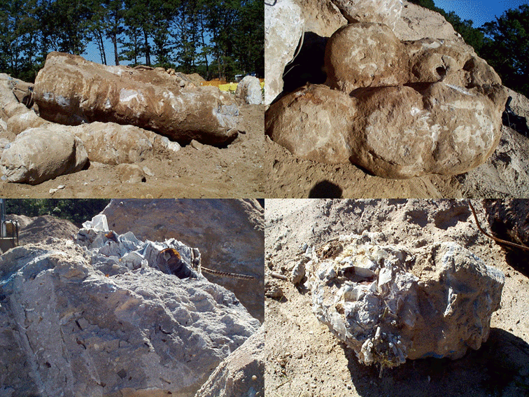
Figure 3. Excavated Pieces of the In-situ Stabilized Waste Form From Pit G-11 at Brookhaven National Laboratory.
POST EXCAVATION EXAMINATION OF THE WASTE FORM
After the excavation ten large pieces from the monolith were set aside for further inspection. These pieces were from 0.5 to 2 M3 each. MSE-TA, Inc was tasked by DOE to perform the visual inspection, coring and cross-sectioning of the monoliths. The ten waste forms were moved to a safe work area where they were inspected and photographed. Due to the health and safety concerns of the material being sampled Class B personnel protective clothing was required for all work. BNL health and safety officers provided coverage (e.g., air sampling, radiation monitoring, etc.) during all aspects of the sampling. Cross-sectioning of the large pieces was performed using a CASE excavator with a chisel hammer.
For the most part the bottles and glassware in the pit were broken up by the energy of the jet (Figures 3 and 4), however in many cases bottles (but no laboratory glassware) appear to be relatively intact. The degree of consolidation was very good, the cement grout kept the waste together for easier removal. Small pieces of waste such as syringes were encapsulated by the grout. There were no major voids observed (greater than fist sized) and later coring would prove there were very few small voids (1 to 10 cm). Overall the degree of mixing was very good and the encapsulation efficiency extremely good.
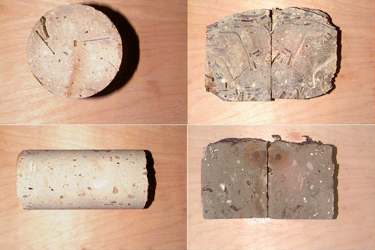
Figure 4. Core Sections Taken From the In-situ Stabilized Waste Form From Pit G-11 at Brookhaven National Laboratory.
What did become apparent was that plastic bottles and apparatus fared much better than the brittle glass. The high pressure grout jet appears to have been capable of breaking up most of the glassware and encapsulating parts. Plastic bottles in a few cases merely collapsed and were encased in the cement.
Waste types such as plastic sheet, plastic tubing, copper tubing, stainless steel tubing, coated wire and similar materials had poor adhesion to the cement grout. The pieces would be fully encapsulated, however wherever the cross-sectioning encountered such debris the pieces would shear along the contact faces of this material.
Core samples were taken from the monolith remnants to gain a better picture of the success of the stabilization. Coring was accomplished using a Milwaukee 4035 electric core drill and a 10cm (4 in), diamond tipped core barrel. The core barrel was lubricated and cooled by water supplied from a truck mounted tank. Three cores were taken from each of the ten waste pieces. They varied in length from 10 cm to 25 cm. The cores were returned to the laboratory, trimmed square, density measurements taken and one core sample from each large piece was stored for future testing. Densities are given in Table I. Subsamples from each of the ten pieces were composited and sent out for RCRA metals analysis following the EPA Toxicity Characteristic Leach Procedure. The results were below the EPA limits for all RCRA metals. One core sample form each of the ten sets was cross-sectioned along the long axis using a wet diamond saw. Inspection of these sections showed good homogeneity, a well mixed product and most importantly virtually no voids. Only a few small (<1cm) voids were seen in the ten cores. Typical core and cross-sections are shown in figure 4.
Table I. Densities of Core Samples from the Pit G-11 Stabilization
| Core sample ID | Density (g/cm3) | Core sample ID | Density (g/cm3) |
1A |
1.78 |
6A |
1.77 |
1B |
1.63 |
6B |
1.88 |
2A |
2.06 |
6C |
1.67 |
2B |
1.98 |
7A |
1.85 |
2C |
2.02 |
7C |
1.76 |
3A |
1.80 |
8A |
1.78 |
3B |
2.11 |
8B |
1.84 |
3C |
1.92 |
8C |
1.85 |
4A |
2.00 |
9A |
1.80 |
4B |
1.94 |
9C |
1.64 |
4C |
1.87 |
10A |
1.99 |
5A |
1.92 |
10B |
2.01 |
5B |
1.85 |
10C |
1.98 |
5C |
1.90 |
||
Average density = 1.87 ± 0.12 |
|||
Median density = 1.86 ± 0.10 |
|||
Four cement/soil samples, 4.4 cm (1.75") diameter, were measured for hydraulic conductivity, the lengths ranged from 3.5 to 4.0 cm. These samples were taken from the containment barrier wall to obtain "clean" samples where there was no observable waste. This allows at least a baseline hydraulic conductivity for the cement/soil composite that encapsulates the waste. The hydraulic conductivities were measured using a flexible wall permeameter following ASTM D-5084 [3]. Conductivities ranged from 1.1 x 10⁻⁶ cm/sec [1.1 x 10⁻⁸ M/s] to 1.6 x 10⁻⁸ cm/sec [1.6 x 10⁻¹⁰ M/sec], averaging 3.4 x 10⁻⁷ cm/sec [3.4 x 10⁻⁹ M/sec].
CONCLUSIONS
In-situ stabilization appears to have produced a reasonably well homogenized waste form. Smaller components such as bottles, glassware, syringes, etc were either broken up by the jet energy or were fully encased in grout. Larger components such as 55 gallon drums and pressure cylinders were left intact by the jet and were simply macroencapsulated.
The large monolithic waste form constructed from the pit contents using jet grouting with cement grout had to be resized for removal and disposal. Bristar demolition grout had no noticeable effect on the cement matrix and is not recommended for future use in waste form resizing.
ACKNOWLEDGMENTS
This work was funded by the U.S. Department of Energy, Office of Science and Technology and was a joint effort between Brookhaven National Laboratory’s Environmental & Waste Technology Center, Sandia National Laboratory, BNL’s Office of Environmental Restoration and MSE-TA, Inc., Butte, Montana.
REFERENCES