
INTEGRATED DEMONSTRATION OF MOLTEN SALT
OXIDATION WITH SALT RECYCLE FOR
MIXED WASTE TREATMENT
Peter C. Hsu, David L. Hipple, Dwight V. Squire,
Erica H. von Holtz, Robert W. Hopper, and Martyn G. Adamson
Lawrence Livermore National Laboratory
P.O. Box 808
Livermore, CA 94551-0808
ABSTRACT
Molten Salt Oxidation (MSO) is a thermal, nonflame process that has the inherent capability of completely destroying organic constituents of mixed wastes, hazardous wastes, and energetic materials while retaining inorganic and radioactive constituents in the salt. For this reason, MSO is considered a promising alternative to incineration for the treatment of a variety of organic wastes. Lawrence Livermore National Laboratory (LLNL) has prepared a facility and constructed an integrated pilot-scale MSO treatment system in which tests and demonstrations are performed under carefully controlled (experimental) conditions. The system consists of a MSO processor with dedicated off-gas treatment, a salt recycle system, feed preparation equipment, and equipment for preparing ceramic final waste forms. This integrated system was designed and engineered based on laboratory experience with a smaller engineering-scale reactor unit and extensive laboratory development on salt recycle and final forms preparation. In this paper we present design and engineering details of the system and discuss its capabilities as well as preliminary process demonstration data. A primary purpose of these demonstrations is identification of the most suitable waste streams and waste types for MSO treatment.
INTRODUCTION
The Department of Energy's Office of Environmental Management is funding research that will identify alternatives to incineration for mixed wastes. (Mixed wastes are defined as waste streams which have both hazardous and radioactive properties.) One such project is Lawrence Livermore National Laboratory's Expedited Technology Demonstration of Molten Salt Oxidation. The goal of this project is to conduct an integrated demonstration of MSO, including off-gas and spent salt treatment, and the preparation of robust solid final forms. This demonstration will include the destruction of organic liquids and organic solids with maximum dimension on the order of 3 mm (for injection purposes). Candidate DOE low-level mixed waste streams for eventual treatment with the MSO technology at another location include spent solvents, oils, and other organic liquids; crucible graphite and activated carbon; plutonium-contaminated leaded gloves; and used ion exchange resins. A successful demonstration of this technology will also be of interest to those responsible for the disposal of medical wastes and military (Department of Defense) wastes.
Molten Salt technology is not new. Rockwell used the process approximately 20 years ago for coal gasification. During that period, they also demonstrated the effectiveness of molten salt for destroying hazardous organics such as PCBs and TCE. Extensive experience on laboratory-, bench-, and pilot-scale MSO units has been obtained at ETEC, LLNL, ORNL, and Rockwell since the technology’s introduction [1,2,3]. Within the last five years, molten salt has been demonstrated as an effective method for the destruction of mixed waste oils and energetic materials [4]. DOE considered the technology mature enough to be implemented into a pilot-scale unit which will be operated during FY 98.
PROCESS DESCRIPTION
MSO is a robust thermal treatment process for destroying organic waste. In this process, organic -containing wastes are injected with a stoichiometric excess of oxidant air under a pool of molten carbonate salts at temperatures between 700–950°C. Flameless oxidation takes place within the salt bath converting the organic components of the waste into CO2, N2,and water. The product off-gas leaving the processor is treated to remove any entrained salt particulate and essentially all water vapor before being discharged to the facility off-gas system. Halogens and heteroatoms such as sulfur are converted into acid gases, which are then "scrubbed" and trapped in the salt in forms such as NaCl and Na2SO4. Using sodium carbonate in the processor, this process occurs according to the reaction shown in Equations 1, 2, 3, and 4, where X represents generic halogens.
2CaHb + (2a+b/2)O2 ® 2aCO2 + bH2O |
(1) |
For nitrogen -bearing organic wastes,
CaHbNc + (a+b/4)O2 ® aCO2 + b/2H2O + c/2N2 |
(2) |
For halogenated organic wastes,
CaHbXc + c/2Na2CO3 + (a+(b-c)/4)O2 ® (a+c/2)CO2 + b/2H2O + cNaX |
(3) |
For sulfur-containing organic wastes,
| CaHbSc + cNa2CO3 + (a+b/4+3c/2)O2 ® (a+c)CO2 + b/2H2O + cNa2SO4 | (4) |
Other non-oxidizable inorganic constituents, heavy metals, and radionuclides are held captive in the salt, either as metals or oxides, and are easily separated for disposal.
MSO has several advantages over incineration. The large thermal mass of the molten salt provides a stable heat-transfer medium that resists thermal surges and ensures temperature uniformity and is therefore able to tolerate rapid process fluctuations. Flame-outs are completely avoided, since MSO is a non-flame process that proceeds by catalytic liquid-phase oxidation reactions. MSO generates less off-gas than incineration, since it does not require supplemental fuel to sustain a flame. Operation of the MSO system is at temperatures hundreds of degrees lower than flame combustion temperatures, which, among other things, minimizes emissions of the radioactive materials from mixed wastes. Acid gases are "scrubbed" by the alkali salts, eliminating the need for a wet off-gas scrubbing system. Also, permitting the MSO process should be easier since it is not an incinerator; permits for the construction and operation of incinerators are difficult to obtain, and public opposition to incinerators can be strong.
SYSTEM DESCRIPTION
The integrated MSO system, shown in Figure 1, consists of several subsystems. It includes a reaction vessel, an off-gas treatment system, a salt recycle system, feed preparation equipment, as well as ceramic final waste forms immobilization system. The feed preparation area includes waste receiving drums, centrifuge for solid liquid separation, a shredder for size-reducing solid wastes such gloves, booties etc. The waste is fed to the reaction vessel along with oxidant air using a top-feed injection system designed for solid and liquid waste streams at throughputs up to 7 kg/hr for chlorinated solvents. Product off-gas exiting the vessel is then treated in the off-gas system to remove entrained salt particulates, water vapor, and traces of gas species such as CO and NOx, As waste is injected into the MSO vessel, residues of inorganic components build up in the salt bed which necessitates periodic removal of salt and replenishment with fresh salt to maintain process efficiency. Because many of the metals and/or radionuclides captured in the salt are hazardous and/or radioactive, without further treatment the removed spent salt would create a large secondary waste stream. A salt recycle system is needed to segregate these materials to minimize the amount of secondary waste, and to reduce the consumption of fresh salt [5, 6]. The segregated inorganic residues are then encapsulated for final disposal. Each subsystem is described below.

Figure 1. Integrated MSO System
Reaction Vessel
The MSO reaction occurs in a 2.74 meter tall processor vessel, shown in Fig 2. The processor is 38.1 cm inside diameter over the top half and 29.8 cm inside diameter over the bottom half, with a 30.5 cm long, tapered transition zone in between. The normal salt load is 160 kg and fills the vessel to the bottom of the transition zone when quiet. When air and feed injection is occurring, the salt level froths up to the top of the transition zone. The freeboard area of the vessel above the salt level provides a dis-engagement zone for salt spray to separate from the off gas before it exits. There are baffles in this region to assist in separating the salt spray. The air and feed material enter through an injector lance extending through the vessel cover to the bottom of the vessel. The injector is insulated and air cooled to keep the feed temperature low until it leaves the injector and contacts the molten salt.

Figure 2. MSO Reaction Vessel
The vessel is fabricated from 1.27 cm thick Inconel 600Ò material. Corrosion tests at LLNL have shown an acceptable corrosion rate for Inconel 600Ò in Na2CO3 and NaCl salt mixtures at operating temperature. The most severe corrosion attack is due to NaCl, so the life time will be shortened by high NaCl content. The vessel is protected against overpressure by placing close limitations on maximum feed rates, by closely monitoring the offgas system to prevent build up of salt deposits that may cause plugging, and by a rupture disk on a dedicated vessel nozzle. The rupture disc is a low pressure disk that discharges into a separate exhaust vent stack.
The vessel will expand about 3.8 cm over its length when at operating temperature. To permit this, the vessel is held from the top and mounts on a free standing structural support stand. The heaters are radiant electric type and are made up of two major subassemblies: one assembly covering the top half of the vessel and a second subassembly covering the bottom half. The heaters are separately supported from the vessel support stand. The vessel has a salt drain pipe extending from the bottom of the vessel to outside the heated zone. A plug of frozen salt will be established in the salt drain pipe, and when the spent salt is to be removed from the vessel, a separate heater will be turned on to melt the salt in the drain pipe. At that point, the entire salt contents of the vessel will discharge through the salt drain pipe into a collection pan. The collection pan is inside a special canister that contains any salt splashing and misting that may occur. After the salt has cooled, the entire canister with its salt contents is moved to the salt recycle area for extraction of the (now frozen) salt. The vessel temperature is maintained by the control system. The heaters are segregated into several zones, each of which is separately controlled to a temperature determined by sensors mounted in blocks on the outside of the vessel. When exothermic materials are being fed, the vessel must be cooled to prevent overheating. A blower is provided for this which blows ambient air though the annular space between the heaters and the vessel wall.
Off-gas System
The purpose of the off-gas system is to remove entrained salt particulates, moisture, and traces of CO and NOx from the off-gas and ensure that clean gas exists the off-gas system. This is accomplished by the following components: a piping section with a gas-to-air cooler, an air cylinder and salt trap, a ceramic filter, a heat exchanger and condenser, an electrical heater, a HEPA filter, and catalytic converter. Figure 3 shows the off-gas system.

Figure 3. Off-gas System
The off-gas exiting the reaction vessel is first cooled to 500° C by the gas-to-air cooler. The gas-to-air cooler consists of two concentric pipes with an annular gap between them. Compressed air flows through the annular gap and cools the gas flowing through the inner pipe. As the gas stream cools, the entrained salt cools and sticks to the inner pipe wall. Salt buildup is removed by a wire brush on the end of a rod that is driven and retracted by the air cylinder. The dislodged salt falls into the vessel on the forward stroke and falls into the salt trap on the reverse stroke. The smaller entrained particles are captured in the pulsating, self-cleaning ceramic filter. The ceramic filter captures particles ° 0.5 micrometers in size and can withstand gas temperatures up to 700° C. Six, silicon carbide filter elements are pulsed with compressed air to remove caked on salt when the pressure drop across the elements reaches 2.74 kPa (11 inches water). The captured salt in the salt trap and ceramic filter is removed by cycling double dump valves that allow the salt to fall into a drum below them. The double dump valves are used to isolate the negative system pressure from the atmospheric drum pressure. The gas is kept at about 300° C to ensure that the gas is well above the dewpoint (50° C) to avoid any water condensation and that the salt remains dry.
The filtered off-gas is then cooled to 100° C by a shell and tube heat exchanger using LCW. The moisture is removed when the gas is cooled to 2° C by the condenser using propylene glycol from a chiller. The gas is then heated to 30° C by an electrical heater to ensure dry gas enters the HEPA filter. The HEPA filter serves two purposes. It acts as a pre-filter for the catalytic converter and a barrier for remaining particles in the off-gas. Thus no salt particles escape the process off-gas system. The catalytic converter is designed to abate 50,000 PPM of CO and 30,000 PPM of NOX. It converts CO into CO2 in a catalyst bed at elevated temperatures. It also is equipped with an ammonia injection system that converts NOX into N2 and H2O by selective catalytic reduction. The off-gas leaving the catalytic converter is very clean and is exhausted to a building stack via a ducting system.
Salt Recycle System
The salt recycle system, shown in Fig 4, receives spent salts from MSO processor and off-gas system. The amount of spent salt received is about 160 kg. The size of spent salt is reduced to approximately 6.3 mm by using hand tools, air-power tools, and a crusher; which are all done inside an enclosure. Small salt particles are then transferred to tank T-101 by a spiral conveyor. Salt samples will be taken during salt crushing for analysis. Salt dissolution will be performed in tank T-101 using either deionized or clean recycled water. The salt dissolution step will be controlled at 30–40°C by an immersion heater and a temperature controller to minimize the amount of water required. Most of mineral residues and ashes will precipitate as hydroxides and oxides during the dissolution step. Chemical reagents such as sodium hydroxide, hydrochloric acid, and dithionite will be used at various stages of the process to adjust pH and/or facilitate metals removal. Reagents such as Alum [Al2(SO4)3] and activated silica will be added to facilitate the coagulation & precipitation process to avoid an excessive holding time in the dissolver tank. These reagents can be fed into the T-101 or T-102 by metering pumps or by opening the hatch.
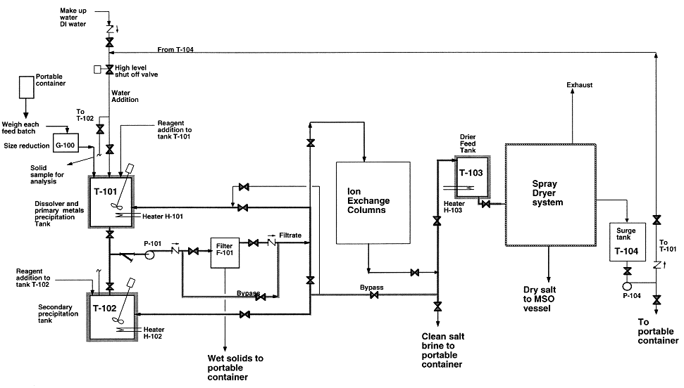
Figure 4. Salt Recycle System flow diagram
Once precipitated, these solids can then be removed by pumping the solution through F-101. The filter has a filter element of 1 micron and will efficiently remove solid particles from the salt solution. The filter element may be pre-coated with a thin layer of diatomaceous earth to facilitate the filtration process. At various stages, the filter cake will have to be removed by opening the filter vessel and relocating the filter cartridge into the wash-off area inside the enclosure. Air and water will be used to assist the cake removal. The wet cakes are then sent to the Final Forms for immobilization. The filtration operation is performed inside an enclosure.
After metals precipitation, the salt solution will go to a spray dryer, ion exchange columns, and/or portable containers, depending on the concentrations of carbonate and radionuclides. If the spent salt contains high level of carbonate, then the solution will be pumped to T-103 for spray drying. If it contains low levels of carbonate and traces of uranium and thorium, then the salt solution will be pumped to the ion exchange columns E-101/E-102 for removal of radionuclides. In some instances, the salt solution will be pumped to portable containers and shipped to Hazardous Waste Management (HWM) of LLNL.
The spray dryer is part of the salt recycle system. It receives clean salt solution from T-103. The system includes a natural gas-fired air heater, a dryer using hot air as heating medium, a cyclone separator for collecting clean dry salt, and a venturi scrubber as well as an absorber for gas cooling and dust control. The clean dry salt will be collected in well-sealed drums for reuse. The air leaving the absorber passes through a HEPA filter and exhausts. The spray dryer is operated at a slight vacuum. Condensate blowdown is pumped to T-104 for reuse or discharge.
Ceramic Final Forms
The wet filter cake produced by the salt recycle system will contain residues from the MSO process itself, typically deriving from a variety of input waste, and compounds introduced by the salt recycle process. In addition to metals and oxides, there may be some carbonates, phosphates, sulfates, sulfides, borides, carbides and nitrides. Overall, LLNL residues are expected to be dominated by Si, Al, Mg, Zn, Ca and Fe. Any of a wide variety of elements may be present in minor or trace amounts. The ceramic final waste form must immobilize the hazardous and radioactive elements present; both the ceramic material and the process to make it must be adaptable to the variable composition of the filter cake; and a high waste loading is desirable. The ceramic is intended to satisfy federal and California leach resistance standards.
The ceramic material is described in Section "EXPERIMENTS AND RESULTS" and in Ref. 10. Briefly, the ceramic comprises several crystalline phases. They were chosen because (1) they can be fabricated as a durable ceramic using standard and economical ceramic processing methods; and (2) because they can incorporate, either as major constituents or by ion substitution, all of the dominant elements just mentioned, and most of the hazardous and radioactive elements of concern. A recipe is calculated for each residue batch (i.e., filter cake), based on its elemental content. Waste loadings should be optimized by blending residue batches, but this is precluded from the demonstration by the paucity of filter cakes produced.
The main equipment items are as follows:
The system also includes a variety of quality-control, process-control and lab-scale processing equipment. Control is local to each equipment item; process monitoring and data collection is direct to the Final Forms computer. Suitable hazards controls will be in place. In particular, the powder processing steps are conducted in closed equipment or in fume hoods to avoid dispersion of the powders; and monitoring equipment will measure the level of radioactivity and the particle concentration in the work stations and area. All exhaust gases pass through local HEPA filters prior to entering the building exhaust system. The only unattended operation is sintering. The system is capable of producing ~2 Kg of ceramic waste form per 8-h working day, in the form of cylindrical pellets approximately 9 mm dia ´ 7 mm tall. The production capacity is limited by the sintering step: it could be doubled by adding a second tube furnace. Scaling up to more than about 10 Kg per day would best be done by using a continuously-fed tunnel kiln.
The process consists of the following operations (see Fig. 5):
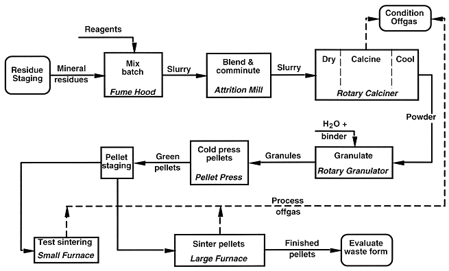
Figure 5. Ceramic waste form process functional flow diagram.
Wastewater streams generated are not shown.
Simple process-control tests accompany the above steps. Until the pellets are sintered, errors are easily corrected by recycling the batch through the process. To avoid more intractable errors (such as pellets melted together) and also to optimize the sintering, a few pellets from each batch are sintered in the small furnace prior to step No. 5. During the final soak, the furnace is operated in a temperature-gradient mode with pellets located at several temperature positions. The soak temperature for step No. 5 is based on the results.
Secondary waste streams include offgas, vaporized solids trapped from the offgas, aqueous liquid wastes (including filtrates from clean-up slurries and offgas condensates ), and powders. Some of the solids are incorporated into subsequent ceramic batches; others, and the aqueous liquids, are disposed as hazardous or mixed waste by LLNL’s Hazardous Waste Management. (We originally had intended to immobilize the trapped solids by microencapsulation in sulfur-polymer cement, but this was deleted from the project for cost reasons.) The quantities of offgas (H2O, HNO3, CO2, CO, NOx, SOx) generated by the Final Forms system are far below regulatory limits, but some conditioning is done prior to release.
EXPERIMENTS AND RESULTS
This integrated system was designed and engineered based on laboratory experience with a smaller engineering-scale unit and extensive laboratory development on salt recycle and final forms preparation. This section reports some experimental results.
Engineering Development Unit (EDU)
The engineering development unit was built in 1995 with the principal goal of verifying the MSO technology with several model feeds at a meaningful engineering scale before an integrated pilot scale facility was designed and built. It became operational in the Summer of 1995. It was run for several hundred hours from Summer 95 to Spring 96 with several model feeds and valuable technical data were obtained. Several species such as O2, CO, CO2, NOx, and THC (total hydrocarbon) in the off-gas were monitored continuously during the course of experiment and some of the results are shown in Table I, Fig. 6, and Fig. 7. Table I. shows average concentrations of several species in the off-gas at various operation temperatures and chlorine levels in the salt melt. Concentrations of CO and NOx decrease as temperature increases. Cl level in the salt melt seems to have a minor effect on the concentrations of CO and NOx, although its effect is not as profound as that of temperature. Concentration of THC is very small in each case, an indication of high process efficiency. Process efficiency is defined as
|
(5) |
where Mc,in and Mc,out are total organic carbon in the feed and in the off-gas, respectively, g organic carbon/min. Oxidation is complete when the process efficiency reaches 100% (i.e. no organic carbon in the off-gas). Table I indicates that the process efficiency was at or greater than 99.9999%. Figure 6 shows the concentrations of several species in the off-gas at 951 oC and gas velocity in the MSO processor at 1 ft/s. Concentrations of gas species seemed to be stable during the experiment except CO. Pyridine is a nitrogen-bearing organic and was chosen as one of the model feeds to verify NOx level in the off-gas. As expected, NOx was high as shown in Fig. 7 with the pure pyridine feed. With installation of catalytic converter in the off-gas system, NOx level in the off-gas would drop to less than 200 ppm.
Table I. Effect of Chloride Level on the Quality of Off-gas
Mineral Oil/Toluene as model Feed, at Vs = 0.3 m/s and 30% Excess Air
C1 Level |
Target T |
% O2 |
Ppm CO |
% CO2 |
PpmNOx |
Ppm THC |
Organic Carbon In the Off-gas g/min |
|
0 |
880 |
4.50 |
26.23 |
12.16 |
123.71 |
0.01 |
6.8 x 10 -7 |
>99.9999 |
0 |
925 |
4.82 |
23.29 |
12.22 |
55.76 |
0.02 |
1.4 x 10 -6 |
>99.9999 |
0 |
950 |
4.76 |
20.47 |
12.33 |
59.35 |
0.06 |
4.1 x 10 -6 |
>99.9999 |
12.9 |
850 |
4.25 |
294.33 |
12.28 |
147.30 |
0.11 |
7.5 x 10 -6 |
99.9999 |
12.9 |
900 |
4.43 |
122.91 |
12.05 |
94.18 |
0.08 |
5.4 x 10 -6 |
>99.9999 |
12.9 |
950 |
4.31 |
51.11 |
12.39 |
79.02 |
0.09 |
6.1 x 10 -6 |
>99.9999 |
43.3 |
850 |
5.22 |
205.07 |
11.89 |
241.62 |
0.10 |
6.8 x 10 -6 |
>99.9999 |
43.3 |
900 |
5.31 |
282.64 |
11.51 |
88.38 |
0.11 |
7.5 x 10 -6 |
99.9999 |
43.3 |
950 |
5.24 |
160.48 |
12.32 |
78.50 |
0.11 |
7.5 x 10 -6 |
99.9999 |
62.8 |
800 |
4.56 |
936.26 |
11.54 |
250.07 |
0.16 |
1.1 x 10 -5 |
99.9999 |
62.8 |
850 |
4.52 |
732.50 |
11.52 |
126.52 |
0.17 |
1.2 x 10 -5 |
99.9999 |
62.8 |
900 |
4.45 |
475.35 |
11.55 |
108.87 |
0.13 |
8.8 x 10 -6 |
99.9999 |
62.8 |
950 |
4.39 |
161.75 |
12.20 |
106.82 |
0.11 |
7.5 x 10 -6 |
99.9999 |
*Notes: average values during the course of experiment
organic carbon feed rate 7.8 g/min
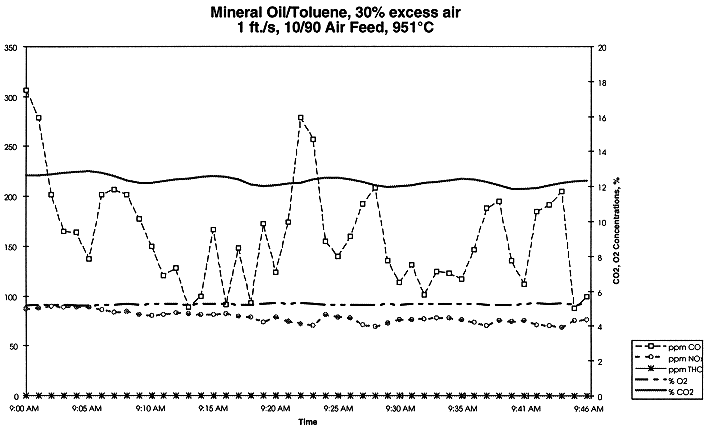
Figure 6. Concentrations of Several Species in the Off-gas for EDU Experiment with 43.3% Chloride in the Salt Melt
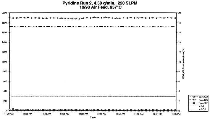
Figure 7. Concentrations of Several Species in the Off-gas for EDU Experiment with Pyridine
Salt Recycle Process
LLNL has developed a process and built a pilot-scale system to separate metals, mineral residues, and some radionuclides from surrogate salts and spent salts generated by MSO reaction vessel. This process includes salt dissolution, pH adjustment, chemical reduction, coagulation, filtration, ion exchange, and drying. The process uses dithionite to vary oxidation states of several metals in order to suppress solubilities of metal compounds in water. This process is capable of reducing the secondary waste to less than 5% of its original weight. It is a low temperature, aqueous process and has been successfully demonstrated in the laboratory . Fig. 8 shows the process flowsheet of salt recycle system.
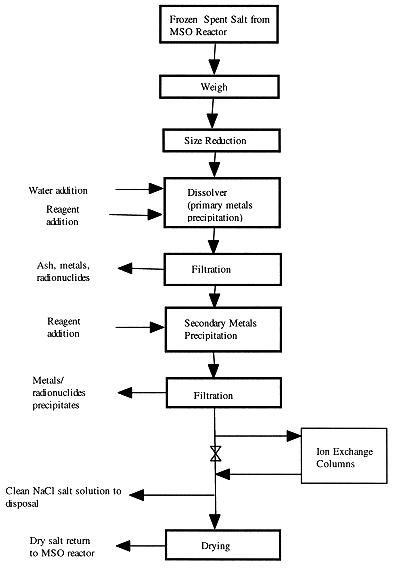
Figure 8. Flowsheet for Aqueous Processing of Spent Salt
Salt melt withdrawn from the MSO reaction vessel is frozen and cooled to ambient temperature. The spent salt is then size-reduced to about 6 mm to avoid excessive dissolution time. Most of mineral residues in the spent salt have low solubilities in water, depending on solution pH values, and will precipitate as metal oxides and metal hydroxides during the dissolution step. Table II shows optimum pH value that will minimize the solubility for each metal species in the solution. Therefore, it is desirable to maintain the solution pH values in the dissolver above 8 to minimize the concentrations of soluble metal species in the solution.
Table II. pH Values for Minimum Solubility
| Metal species | pH at minimum solubility |
| Beryllium | 9.2 |
| Cadmiun | 11.6 |
| Chromium (Cr3+) | 8.0 |
| Copper | 9.0 |
| Lead | 10.6 |
| Mercury | 14.0 |
| Nickel | 10.8 |
| Plutonium | 7.8 |
| Silver | 14.0 |
| Uranium | 6.2 |
| Zinc | 9.4 |
Addition of other reagents may be required in separate steps to convert the valence state of dissolved metals into insoluble forms. For example, use of dithionite in the secondary metals precipitation step reduces soluble Cr6+ to Cr3+, with subsequent formation of the insoluble species Cr(OH)3/Cr2O3. Solubilities of chromium hydroxide and chromium oxide vary with pH, but are very low in alkaline solutions.
As the metals come out of solution in all stages, they tend to form
submicron size particles. Reagents such as Alum [Al2(SO4)3]
can be very effective in facilitating coagulation and precipitation to avoid an excessive
holding time in the dissolver tank. The addition of coagulant aids such as activated
silica will enhance coagulation by promoting the growth of large, rapid-settling flocs.
Activated silica is a short-chain polymer that serves to bind together particles of
microfine aluminum hydrate. Table III shows that alum and activated silica reduce the time
required for the start of precipitation from 85 minutes to 25 minutes for a spent salt
containing 20% NaCl, 78.8% Na2CO3, and 0.2%
Na2CrO4 dissolved in water with 1% dithionite added for the chrome
reduction.
Table III. Time Required for Precipitation is Reduced With Addition of Alum and Activated Silica
Run ID |
Coagulant |
Coagulant aid |
Time, Minutes |
S |
0 |
0 |
85 |
C1 |
0.015 |
0.001 |
75 |
C2 |
0.15 |
0.01 |
25 |
Filtration of the salt solution occurs after initial dissolution, for "ash"/mineral residue removal, and after addition of reagents to further remove dissolved metal species. Selection of an appropriate filter element is crucial for complete capture of suspended solid particles. The pore size of the filter element should be one micron or less for high capture efficiency. After the secondary metals precipitation and subsequent filtration, the salt solution is very clean and can be dried and reused if it contains a significant level of carbonate (> 20 wt%).
The salt recycle process has been demonstrated successfully with EDU spent salt.. X-ray Fluorescence (XRF) was used to determine the elemental composition of the spent salt, which is shown in Table IV.
Table IV. Elemental Composition of EDU Spent Salt
Element |
Composition, wt% |
Element |
Composition, wt% |
C |
0.99 |
0 |
1.98 |
Na |
38.69 |
Si |
0.04 |
P |
0.01 |
S |
0.08 |
Cl |
57.54 |
K |
0.01 |
V |
0.014 |
Cr |
0.48 |
Mn |
0.03 |
Fe |
0.04 |
Ni |
0.04 |
Cu |
0.03 |
Br |
0.00 |
Mo |
0.02 |
Pt |
0.01 |
Table IV indicates that the spent salt contains about 95 wt% sodium chloride along with minor amounts of several metals. Many of the metals present are at levels exceeding the RCRA land-ban criteria and this salt would be considered a hazardous waste if disposed of without further clean-up.
The spent salt was then dissolved into water and solution samples were taken for analyses after the primary metal precipitation step and the secondary metal precipitation step. Table V shows the results. Concentrations of soluble metal species in the salt solution after the primary metal precipitation step , except Cr6+, are very low due to their low solubilities in water. Further removal of chromate ion Cr6+ can be achieved in the secondary metal precipitation step by using dithionite.
| 2CrO42-+ S2O42-(excess) + 4H2O ® 2Cr(OH)3 + 2SO42- + 2OH- | (6) |
Chromium hydroxide, a green gelatin-like solid, precipitated as a result of the reaction. Excess dithionite is normally required to improve the conversion efficiency. Concentration of Cr6+ dropped to < 1 ppm from > 500 ppm, indicating that dithionite is an excellent reagent to remove chromium from the solution. Table V also shows that sulfate ions in the solution, a benign species which should not be a concern, increased from 200 ppm to 2600 ppm after the secondary metal precipitation step.
Table V. Concentration of Soluble Species in Salt Solution
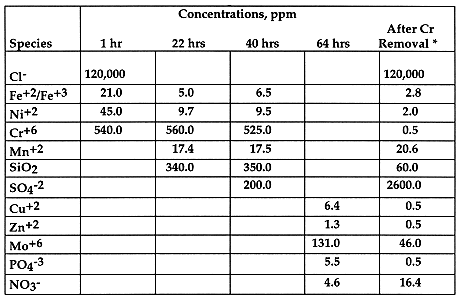
Table VI shows concentrations of several key metal species after the clean-up process,. It indicates that very clean dry salt can achieved after the process; concentrations of metal species in the salt are mostly less than 100 ppm, some are in ppm.
Table VI. Key Metal Species in Clean Salt Solution
| Species | In solution |
Concentrations, ppm |
| Fe | 2.8 |
13.9 |
| Ni | 2.0 |
9.9 |
| Mn | 20.6 |
102.0 |
| Cu | 0.5 |
2.5 |
| Zn | 0.5 |
2.5 |
| Cr** | 0.5 |
2.5 |
| Mo | 46.0 |
228.0 |
| As* | 0.5 |
2.5 |
| Se* | 0.9 |
4.5 |
| Ba* | 0.04 |
0.2 |
Be,Cd,Pb,Ag,V,Co,Tl were undetectable by ICP/MS
*measured by ICP/MS, total chromium was about 6 ppm due to small particles of chromium hydroxide, Cr(OH)3 , which passed through the 2.7 micron filter. Use of finer pore-size of filter element should eliminate this problem.
Radionuclides Removal From MSO Spent Salts
If the MSO processes waste feed which contains radionuclides, the radionuclides will be captured and held in the salt. Most radioactive compounds would co-precipitate with ash/mineral residue and will be removed from the salt solution after the dissolution and first filtration step. Some radionuclides, such as thorium and uranium, form complex ions and stay in the solution. For example, predictions using EQ 3/6 indicate on the order of 300 ppm of uranium, as uranyl complex ion (UO2(CO3)34-), would remain in carbonate solution [7]. However, for salt solution with high carbonate content, most uranium can be removed in the secondary metals precipitation step by adding strong caustic alkali such as sodium hydroxide to break up complex ions as shown in eq. 7.
2UO2(CO3)34- + 6OH- + 2 Na+ ® Na2U2O7 + 6CO32- +3H2O (7)
Table VII shows that over 90% of uranium can be removed by this process.
Table VII. Uranium Removal at Different pH
Initial [U], ppm |
Final [U], ppm |
|
2400 |
190 |
47 |
For salt solutions with low carbonate content, the uranyl carbonato complex ion can be destroyed and converted to UO22+ by adding HCl. Reducing agent is then added to lower the oxidation state of uranium from +6 to +4, as shown in Eq. 8.
UO22+ + reducing agent ® UO2 (precipitates) (8)
Many reducing agents might work and we have found dithionite is particularly effective in this application. Table VIII shows results of uranium removal experiment . It indicates that uranium concentration dropped to below 1 ppm. Over 99% of uranium can be removed by the chemical reduction process.
Table VIII. Uranium Removal by Chemical Reduction.
Initial [U], ppm |
[U] after chemical reduction, ppm |
165 |
0.24 |
2000 |
0.80 |
The residual uranium can then be further removed by ion exchange process. A variety of commercial ion exchange resins are available; Diphonix (made by Eichrom) worked well for our application. Table IX shows that Diphonix is very effective for uranium polishing at pH 5.5. The salt solution at pH 5.5 was pumped around the ion exchange column filled with Diphonix for 1.5 hours and reduced the uranium concentration to 0.03 ppm.
Table IX. Ion Exchange Process for Uranium Removal
Time, hr |
[U] in solution, ppm |
20 |
|
0 |
7.1 |
0.3 |
2.1 |
0.6 |
1.0 |
1.0 |
0.3 |
1.5 |
0.03 |
A thorium removal process also has been developed by our group. We have demonstrated that the majority of thorium in salt solutions can be removed by adding sodium hydroxide and residual thorium can be further reduced using an ion exchange process [9].
Final Forms
A brief account of our ceramic waste form follows; further details may be found in Ref. 10. The ceramic material design is based on Synroc-D [10]. The basic Synroc concept is a ceramic comprising several crystalline phases among which waste ions can partition, either as major constituents or as substitutional solutes. The partitioning is largely determined by ion charge and size. Our ceramic waste form design includes nepheline [NaAlSiO4], spinel [MgAl2O4], zirconolite [CaZrTi2O7] and perovskite [CaTiO3] as the main host phases; rutile [TiO2], which serves as a buffer to ensure ample formation of perovskite and zirconolite; and apatite [Ca5(PO4)3(F,Cl,OH), a probable fate of phosphorous. A small amount of glass is expected but undesirable: it is a good solvent for elements not well-matched to a host phase while having poor chemical durability. Some porosity is inevitable with the chosen processing methods. Connected porosity presumably diminishes leach resistance. We try to minimize the glass and the connected porosity in the ceramic.
As mentioned previously, LLNL residues are expected to be dominated by Si, Al, Mg, Zn, Ca and Fe. In addition, however, a large number of minor and trace elements may be present. Various factors limit the list of chemical elements that plausibly could be present in our ceramic waste form. As examples, transuranic wastes will be excluded from treatment, and As vaporizes. A long list remains. Of these O, Na, Mg, Al, Si, Ca, Ti and Zr are end-member constituents of our mineral phases. Among the remaining elements, Be, F, V, Cr, Co, Ni, Cu, Zn, Mo, Ag, Cd, Sb, Ba, Tl and Pb are of particular interest as being subject to leaching limits in either federal or California regulations. A wide range of radionuclides can be present in trace amounts, but the only ones expected in quantity (>0.1 wt%) are 40K, 232Th, 235U and 238U. Unregulated elements are important for their effects on processing and overall durability.
A few elements of interest are not accommodated by the basic scenario. The regulated elements Hg, As and Se are volatile. They, and much of any Tl present, vaporize and are trapped during processing. Beryllium forms a separate durable phase, while Ag forms metallic inclusions. Fluorine (regulated in California) would be in the –1 state, and S, Mo and W would be in their +6 states; neither charge is among designed host sites. Fluorides could be precipitated as CaF2 during salt recycling, but only small amounts (<1 wt%) can be tolerated in our ceramic. Sulfur and Mo can volatilize as oxides during processing, but they also dissolve in the glassy phase—and probably promote its formation. Boron ions are too small and Ba ions are probably too large to be accommodated in the host phases.
Recipes are designed to achieve maximum loading of the residue into the ceramic, while not exceeding the solid solubility of the minor and trace elements in their host mineral phases or producing less than ~10 wt% of any of the design host phases. The latter requirement ensures a dominant phase assemblage in the presence of the large variety of constituents. A typical recipe is given in Table X. For a typical "combustible" waste stream (e.g., laboratory waste such as paper, gloves, booties, etc.), waste loading is limited to about 40% by the silica, alumina and magnesia in the incoming waste stream. Waste loading may be further constrained by silica introduced during salt recycling.
Table X. Typical surrogate residue recipe (No. 75)
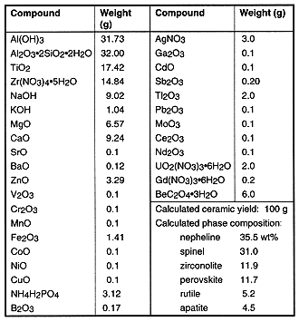
Using bench-scale equipment, we have fabricated over 250 experimental ceramics under a range of processing conditions and containing a wide variety of elements—as many as 46 elements, including 15 of the 18 having leach limits assigned by U.S. or California regulations, in a single formulation. The purposes of these experiments were to investigate the phase formation, microstructure, partitioning, leach behavior, and processing. The resulting materials are rather complex, and interpreting their properties is not simple.
Experimental specimens are characterized by gravimetry (porosity), liquid-intrusion porosimetry (connected porosity), SEM-EDS (microstructure, phase compositions), X-ray diffraction (phase identification), X-ray fluorescence (overall composition, volatility losses), electron microprobe (partitioning), and SIMS (partitioning). A small amount of STEM analysis also has been performed. Trapped volatiles are analyzed with ICP-OES. Leachate analysis is by ICP-OES and ICP-MS. A typical microstructure is shown in Fig. 9.
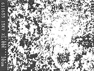
Figure 9. Microstructure of a typical experimental ceramic waste form.
This specimen (No. 191) was sintered for at 1150°C for 24 h to coarsen the structure for characterization purposes. Grain size for normal (1-h) sintering is smaller but otherwise similar. The phases have the following appearance: The white equiaxed grains are zirconolite; the light-gray equiaxed grains are perovskite; the darker-gray elongated grains are spinel; and the darkest gray regions are nepheline. Rutile is not visible, and porosity is black. In addition to the fine-scale porosity visible here, views of this specimen at lower magnifications showed some very large round pores presumable resulting from gas evolution. Scanning electron micrograph (SEM); size bar = 30 µm.
Grains are generally less than one µm in size for one-hour sintering. Density exceeds 90% of theoretical; some of the porosity is connected. The major crystalline phases normally identified are spinel, nepheline, zirconolite, perovskite, and rutile. Spinel is the major host phase for many transition elements. Nepheline incorporates K. Zirconolite hosts Sr, Hf, U, and small amounts of rare earths. Perovskite is the major host for rare earths, and also incorporates Sr and Pb. Ag is found as spheroidal metallic inclusions. When significant levels of phosphorus are present, a calcium phosphate phase is observed as porous, spheroidal inclusions. The stoichiometry does not, however, correspond to either hydroxylapatite [Ca5(PO4)3(OH)] or whitlockite [Ca3(PO4)2]. Possibly the phase is a phosphate glass. A glassy silicate phase is also observed. As one would expect, this phase incorporates those elements that are incompatible with available sites in the phases already mentioned: S, Mo and Ba have been found in the glass, for example. Some elements that have crystalline host phases partition to a lesser degree into the glass as well. Boron has not been isolated but is probably in the silicate glass. Tungsten has not yet been included. Solids condensed from Recipe No. 75 (Table X) process offgas are found to contain large amounts of Tl and minor amounts of Ag, Cd and Pb.
The U.S. Environmental Protection Agency has prescribed the Toxicity Characteristic Leaching Procedure (TCLP) [11] as the test for determining whether a waste is to be classified as chemically toxic. The original leachate concentration standards are known as the "Regulatory Limits." Under certain situations, the TCLP leachate must now also satisfy the "Universal Treatment Standards" (UTS) [12,13] concentration limits. We have scaled the TCLP test down from the specified minimum of sample (100 g) to our pellet size (1-3 g), keeping the solution-to-waste ratio and other parameters as specified. Additionally, our ceramic is currently subject California’s "Waste Extraction Test" (WET), which is more stringent. We have only recently begun testing the ceramic against the WET standard and find it difficult to pass [10]. It may not, however, be representative of conditions in landfills, consequently, the method is currently under reconsideration by the state Department of Toxic Substances Control.
The results for a recent sample of our ceramic are shown in Table XI. As can be seen, this sample easily passed the original TCLP limits and failed the UTS limits only for Pb and (barely) V. We have evidence that at least some of the Pb and V reside in the glass phase, and anticipate that future efforts to minimize residual glass will reduce the release of these elements.
Table XI. TCLP Leaching of a Complex Final Form Ceramic
|
|
Specimen |
|
|
| wt % | ppm | ppm | ppm | |
| Hg | 0 | 0.2 | 0.025 | |
| Be | 0.36 | ~0.010 | 0.014 | |
| Cd | 0.088 | 0.03 | 1.0 | 0.19 |
| Se | 0 | 1.0 | 0.16 | |
| As | 0 | 5.0 | 5.0 | |
| Cr(3+,tot) | 0.068 | <0.05 | 5.0 | 0.86 |
| Pb | 0.082 | 1.33 | 5.0 | 0.37 |
| Ag | 1.90 | 0.06 | 5.0 | 0.30 |
| Tl | (1.79) | 0.02 | 0.078 | |
| Sb | 0 | <0.1 | 2.1 | |
| Ni | 0 | <0.08 | 5.0 | |
| V | 0.68 | 0.24 | 0.23 | |
| Ba | 0.090 | 5.3 | 100. | 7.6 |
| Zn | 2.64 | 0.81 | 5.3 | |
| U | 0.84 | <0.03 |
Modified TCLP (see text), Specimen No. 212. This was a replicate of No. 191, shown in Fig. 9. Both were prepared from Recipe No. 75 (Table X) and sintered at 1150° for 24 h. Normal sintering time is 1 h. The longer time was chosen for specimen characterization purposes. Cation concentrations were calculated from the recipe assuming that all cations are present as oxides, except that Ag is metallic. Volatilization is ignored, so the Tl concentration is much less than shown in the table. Leachate concentrations ("ppm") are actually (mg of element)/(L of leachate). A leachate concentration preceded by a less-than sign (<) implies that the element was not detected, the accompanying value being the detection threshold.
The bench-scale processing was designed, of course, to mimic the pilot-scale process. The difference in scale is large (two orders of magnitude). While adjusting the process parameters of the larger equipment will undoubtedly be time-consuming, scale-up should have little effect on the ceramic properties. The main uncertainties are associated with potential modification of the mineral residues by their residence in the molten salt bath, and the introduction of amorphous silica from the salt recycling system. Either could affect our processing. On the other hand, our pilot operations will be virtually plant-scale; only the type of sintering furnace would need to be changed.
CONCLUDING REMARKS
LLNL built an engineering demonstration unit, EDU, which has been run sucessfully with several model feeds with very high process efficiency. We also have developed a process to clean up MSO spent salts. The process can treat various types of spent salts. We have demonstrated this process in the lab on a spent salt from EDU, which had a high chloride but low ash content. The results show that most metals precipitate out during the dissolution process. Further removal of metals, such as, chromium, thorium, and uranium can be accomplished in the subsequent steps. Futhermore, we have demonstrated the bench-scale fabrication of a polyphase ceramic final waste form designed to immobilize the mineral residues of the MSO system. Individual samples of the ceramic have been made containing as many as 46 chemical elements, including 15 of the 18 regulated ones. Resistance to leaching of regulated elements is generally excellent. In one very complex formulation, only Pb seriously failed the federal UTS limit. This failure may well be eliminated by reducing the amounts of residual glass and porosity in the ceramic. Efforts will be made to satisfy California requirements as they become more certain.
An integrated MSO pilot scale facility that includes Salt Recycle has been designed and built. The facility will be started up and fully operational in November 1997. Treatability studies will be conducted in the LLNL facility with real mixed wastes during Fiscal Year 1998. With knowledge and experience gained from this facility, treatment of a variety of DOE mixed wastes and private-sector hazardous wastes will be possible.
ACKNOWLEDGEMENTS
The authors wish to thank the following people who contributed to this work: Bill Brummond, Paul Curtis, Tim Ford, George Goers, Frank Silva, Gregg Soto, Leslie Summers, Richard Van Konynenburg, and Francis Wang. This work was performed under the auspices of the U.S. Department of Energy by the Lawrence Livermore National Laboratory under contract number W-7405-ENG-48. Funding was provided by DOE/EM’s Office of Waste Management (EM-30).
REFERENCES