
DEVELOPMENT OF REMEDIATION STRATEGY
FOR SPECIAL NUCLEAR FACILITIES
A F McWhirter; A J Wratten
WS Atkins
ABSTRACT
From the mid 1950s until 1994 the United Kingdom's fast reactor research was centred at the Dounreay Experimental Reactor Establishment, located on the North Coast of Scotland (Fig 1).
During construction of the site's liquid effluent discharge system, a vertical shaft was cut into the rock very close to the low cliffs which make up the Northern perimeter of the Site. (Fig 2). This shaft was used for the removal of excavated material during the mid 1950s. When this construction work was completed, the stub tunnel connecting the Shaft with the effluent tunnel was sealed by casting in-situ, a concrete plug. The Shaft was then allowed to fill with groundwater.
It was licensed as an ILW Disposal Facility by the Scottish Office in 1959 and was used routinely from 1960 to the early 1970s for the disposal of unconditioned ILW wastes until an explosion took place in the gas space above the waste column in 1977, since when it has been in a state of care & maintenance.
Although the Shaft is a Licensed Disposal Facility, UKAEA considers that it does not represent an acceptable model for ILW Disposal. In 1993, a study was commissioned to identify possibilities for confining the waste in situ and isolating the Shaft from the surrounding groundwater.
It had previously been supposed that retrieval of the waste would not be a safe option, however, in 1996, UKAEA decided to invite expressions of interest from suitably qualified companies, to identify options for the retrieval, conditioning and storage of the Shaft wastes. Following the successful conclusion of this work, a further series of more exhaustive studies was undertaken, and these concluded in August 1997.
UKAEA is now assessing the results of these studies and has committed to making a proposal to Government by the end of 1997 on the future management of the Shaft.
This paper describes the studies undertaken and presents, in summary form, their results.
BACKGROUND
The Dounreay Shaft is located less than 10m from the top of low cliffs on the Northern perimeter of the Dounreay Site (Figs 1&2). It was constructed for the removal of spoil during the excavation in the 1950s, of a 600m long liquid effluent discharge tunnel.
When the main tunnel was complete, a concrete plug was cast into the connecting tunnel and, in 1959, the Shaft was licensed by the Scottish Office as an ILW Disposal Facility.
Because the original role of the Shaft was as a temporary access route, the sides were unlined and on discontinuation of the pumping regime, the Shaft filled naturally with fresh water to the level of the surrounding water table.
Discharges to the Shaft were made using a variety of flasks. These were engaged on an adaptor at the top of the Shaft and their contents discharged directly into the water some 7m below.
To prevent the escape of contamination into the surrounding rocks, water was pumped from the Shaft to maintain the level at Ordnance Datum -0.8m to -1.6m. This is approximately three meters below the surrounding water table, encouraging a net inflow of water at all depths down the Shaft. (Fig 3)
On 10 May 1977, following gas accumulation in the space above the waste column, an explosion occurred in the air space above the water. This did significant damage to the facilities at the top of the Shaft and since that time, the facility has been subject to a regime of Care & Maintenance.
Over the years, the waste column has compacted and at today's date, it is estimated to contain approximately 700m3 of mixed wastes. A detailed inventory exists however, its completeness cannot be guaranteed and a great deal of work has been done in an effort to provide an acceptable upper bound of the contents, particularly of the fissile species which may be present.
EARLY STUDIES
In the 1980s, it was becoming clear that the Shaft was not a suitable facility for the ultimate disposal of unconditioned waste. At the time however, it was considered impracticable to safely retrieve the waste as the dose uptake by those involved would be unacceptably high.
A study was carried out in 1993 to assess the feasibility of immobilising the waste in -situ and, while this indicated that it was technically possible, there were many problems associated with achieving confidence of the completeness and long term performance of the confinement.
At the same time, fears were expressed about the rate of erosion of the low cliffs around the Shaft and it was calculated that within 400 years, the Shaft top might be breached by the sea.
As a result of the difficulties identified in the study and the apparent impracticability of retrieval, no further development took place until 1996 when it was decided to establish whether the developing experience in mechanical handling in the nuclear industry had reached the point where retrieval might now be possible.
THE PILOT STUDIES
UKAEA invited expressions of interest via the Official Journal of the EU. This attracted some 37 responses. Upon providing these organisations with additional information, they formed themselves into 19 consortia/companies which submitted tenders for pilot studies.
Following the assessment process, contracts were awarded to six consortia whose lead companies were :
These studies lasted six months and at the end of the process, it was demonstrated that not only was it now possible to safely retrieve the waste, but that there were three identified options available.
The most novel approach to emerge from the studies was to freeze the Shaft, its contents and the surrounding rock. Having frozen it, it was proposed to mill out the waste using a large milling bit (Fig 4). Overlapping cylinders of waste would be drilled out and the resulting slurry assayed at the surface, immobilised and stored.
The remaining contractors identified that the presence of the water, its control and turbidity, represented the key to a successful retrieval project. Some proposed to retrieve the material while leaving the Shaft full of water (Fig 5) - the so called 'Wet Retrieval Option', while others felt that it would be better to remove the water progressively as the waste was retrieved, enabling the items to be seen - the 'Dry Retrieval Option.'(Fig 6)
All involved agreed that a key element of retrieval is the control of water and that this required, in addition to an effective barrier, a detailed understanding of the hydrogeology of the area in the environs of the Shaft.
DETAILED STUDIES
It had been anticipated that, following the initial series of studies, one or at most two organisations would emerge as clear leaders and that following this, two more detailed studies would be able to be specified to enable a clear winner to be identified.
In the event, this did not happen. It was found that each company / consortium had strengths in one or other facets of the works and that no-one had a complete solution for all of the problems posed by the Shaft.
It was therefore decided that the second round of studies should be less adversarial and that development contracts would be let to a limited number of consortia to consider different aspects of the project. These companies would, liaise on a frequent basis, facilitated by UKAEA as they were in general not competing.
There were many tasks set for the contractors however, the principal ones are described below :-
1. The specification of a geotechnical monitoring programme for the area around the Shaft. (Golder Associates)
2. Development of the 'Dry Retrieval' option. Associated with this was the need to study methods of reinforcing the Plug. (Framatome)
3. Development of the 'Wet Retrieval' option. (Sonsub)
4. Outline design of a waste assay, treatment, packaging and storage facility. (BNFL)
5. A detailed review of the effects of freezing of the Shaft and its contents as a means of interim confinement of the waste. (Dames & Moore )
6. A similar review to that above but using either a grout curtain or the construction of a secant pile wall. (Sonsub)
GEOTECHNICAL STUDY
The work carried out was in 3 work packages and the results of these are described below.
Work Package 1
This included a comprehensive review of all previous geological, geotechnical, hydrogeological, engineering, radiological and other related work relevant to the D1225 Shaft and its environs. A key aspect of this review was the identification of any significant data gaps that could affect the current understanding of the Shaft and the adjacent geosphere;
Work Package 2
This included the preparation of a series of simple conceptual models that described the historical development of the Shaft and its environs from the situation before any construction work began, through the period of construction and subsequent waste disposal, the 1977 Shaft explosion and up to present day.
These conceptual models were then perturbed by the inclusion of the various Shaft isolation and waste retrieval options currently being considered and their results summarised in a series of colour graphics. An example showing the current situation is shown as Fig 7. An important outcome of this work was the identification of potential water and contamination migration pathways.
The simple conceptual models were then reinforced by the production of a detailed Discrete Fracture Network ( DFN ) model. This included the development of a three dimensional groundwater flow model, based on fracture flow, using the FRACMAN computer code. Model data were generated from earlier foreshore physical mapping work, supported by probabilistic data generated within the modelling package.
The study highlighted the influence of the groundwater/sea water interface, in determining the direction of water flows at depth and that the direction of groundwater flow near the base of the Shaft may be upwards rather than horizontal.
In addition to suggesting a route for the migration of contamination away from the Shaft the model suggested that in the event of there being a region of low permeability within the Shaft waste, that migration times for water from the Shaft to the geosphere could be as low as 100 days.
With some degree of confinement to limit water ingress, the model predicted that by adopting a suitable pumping regime, it could be possible to introduce a significant reverse flow of water through the fissures and into the Shaft, flushing migrant contamination back into the Shaft where it would be collected and treated.
Risk Assessment Modelling
This included an evaluation of contamination migration pathways from the Shaft using the Golders' Repository Integration Programme ( RIP ) computer code. This identified the likely volumes and rates of migration of contamination away from the Shaft and concluded that the quantity of contamination in the very low activity water pumped from the Shaft exceeds that which could migrate through rock fissures by one to two orders of magnitude.
One of the first tasks in the next phase of the work will be to verify this model and if so verified, it will give confidence that the Shaft is not leaking significant contamination and that action to effect an isolation of the Shaft from the environment is unnecessary so long as the final solution is not left too long.
Work Package 3
This involved the development of a two phased programme to investigate the geotechnical, hydrogeological, and radiological setting of the Shaft. The first phase is aimed at providing hydrogeological, geotechnical and groundwater chemistry information in sufficient detail to demonstrate that the Shaft environs are adequately understood to enable a decision on the future of the Shaft to be made with confidence. The second phase focused on the acquisition of data required by contractors to develop and design engineered isolation and / or waste retrieval proposals for the Shaft.
DRY RETRIEVAL
Dry retrieval is an attractive option as the waste is visible. However, as the waste column height reduces and with it the water level, so the hydraulic head across the plug in the tunnel increases and due to the absence of details of the design of this component, its integrity under a head of 65m of water would be difficult to confirm.
Dry retrieval therefore requires some form of reinforcement of the Plug with the potential to increase the cost and complexity of the project. This completed, the Framatome proposal is to reduce the water level by pumping and to expose the top layer of waste. An 'archaeological dig' approach would then be taken in which individual items would be identified, removed and after initial assay, would be transferred to a Waste Treatment Plant.
In order to maintain the distance between the waste column and the retrieval facility as short as possible, Framatome proposed to use a robotic platform (Fig 8). This would be lowered into the Shaft and via extending legs would position and lock itself centrally in the bore before using its inventory of tools to recover the waste and deposit it in a basket which would be lifted from the Shaft by a hoist.
WET RETRIEVAL
Sonsub has used this technique before with success at Kerr's Hollow quarry in the United States where a great deal of nuclear waste was disposed of. One of the main differences between Kerr's Hollow and the Dounreay Shaft is the latter's greater depth and smaller diameter.
The shielding afforded by the water and the lower differential across the plug favour this approach however, the visibility is expected to be poor. Sonsub have countered this by the proposal of an ultrasonic location facility which could be used to identify specific items, remember their location and direct a grab to retrieve them.
Because of the uncertainties associated with this approach in which the grab might seize something very large or a jammed component, the grab itself requires to be large and powerful and its detailed location when operating at the end of a rope up to 65m long it likely to pose significant problems.
WASTE TREATMENT AND STORAGE
Despite the work undertaken to refine so far as possible the inventory of the Shaft, there remain some uncertainties. For example, there is no disposal record which would explain how the Hydrogen build up on May 10 1977 took place and so it is difficult to completely rule out a similar build up in the future.
As the 1977 incident is believed to have arisen as a result of the reaction of a quantity of Sodium (Na) or Sodium / Potassium (NaK) alloy, it is important to ensure that any sealed vessel, capable of containing such material, is opened in a suitable environment to minimise the possibility of another reaction.
Uranium metal, in damp conditions, can form Uranium Hydride (UH3). This material is pyrophoric and on contact with the air, can spontaneously ignite.
The Waste Treatment Plant proposed by BNFL, while complex, is based upon an existing design in operation at Sellafield. Incoming flasks of material would be tipped onto a screen where the sludge would fall through into a slab tank. The individual items would be assayed by a variety of devices including a gamma camera, active and passive neutron detection and x-ray of sealed containers.
Sealed containers would be moved to a special facility with a Nitrogen atmosphere. Alkali metals would be reacted with water vapour in the Nitrogen environment to form Sodium and Potassium Hydroxides which following neutralisation in Hydrochloric acid, can be discharged safely.
Other items would be located in Nirex compatible containers. Grout would be added and the containers lidded and decontaminated. The contained waste would then be transferred to a new ILW store which might be located alongside the treatment plant.
An outline of the Treatment Plant is shown in Fig 9.
SHAFT ISOLATION BY FREEZING
The purpose of the freezing study carried out by Dames and Moore was to establish whether or not freezing is possible or has been successfully carried out in strata similar to that at Dounreay.
The outcome of this was positive and it was established that there was no foreseeable reason why freezing should not be successful.
One of the central questions to be addressed was the extent of heave which may be encountered. It was found that the forces produced in the freezing process would not generate significant heave at the surface however, the effect on the waste column would be difficult to predict.
If milling of the waste in a frozen state is not adopted, it would be necessary to thaw the Shaft out to retrieve the waste. The rock, frozen for a relatively long period, might be weakened leading to an inward collapse of the Shaft. This problem was overcome by the proposal to thaw the material progressively by surface heating using a steam lance. Concrete reinforcing collars would be inserted in the Shaft to support the sides and channels would be left behind these so that water could run down the outside.
When the Shaft was emptied, and the ground allowed to thaw, the expanded fissures in the rock would enhance the water flow into the empty Shaft, carrying with it, contamination which had begun to migrate away.
The study concluded that the approach is feasible and estimated the capital costs of the process and the operational costs which are likely to be significant.
In a later assessment of this option, it was also shown that a limited freeze, in which the Shaft contents and immediate rock surface remain unfrozen while the rock and ground water a meter or so away is frozen, would be possible and might represent an optimum way to control water ingress during the retrieval process without prejucide to the Shaft integrity. (Fig 10)
SHAFT ISOLATION USING SECANT PILES OR GROUT
Both of these options were considered in detail, however, it was quickly found that there are significant risks associated with the grouting option.
First among these is associated with the uncertainties of the locations, dimensions and directions of cracks. Grout injected at high pressure from the surface will find its way through the route of least resistance and this may not be the direction intended. The possibility of the grout mixing with the waste and rendering it immobile is considered to be unacceptably high. Although no formal decision has been taken on the way ahead, it is felt that this option is unlikely to the adopted.
Secant piles are inserted by drilling a series of holes, separated by a small distance. The holes are filled with a selected concrete and when this has set, a further series of holes is drilled between and overlapping with, the original set. When this second set of holes is filled with concrete and allowed to set, a concrete curtain has effectively been constructed around the Shaft.
This is known technology with little technical risk. While the vertical or near vertical upwelling of groundwater may still gain access to the Shaft via the open bottom of the curtain, it is believed that the water ingress to the Shaft would be reduced to a manageable level.
CONCLUSIONS
The Dounreay Shaft, although licensed as a disposal facility for Intermediate Level Waste, is not considered by UKAEA as an acceptable facility against today's criteria.
In 1993, it was felt that it would not be practicable to retrieve the waste from the Shaft and an In-Situ Confinement study was undertaken.
The more recent studies described in this paper, have confirmed that it is after all possible and practicable to safely retrieve the waste from the Shaft, enabling this option to be considered alongside In Situ Confinement.
The studies have shown the importance of a thorough understanding of the geology and hydrogeology of the Shaft while the other studies have revealed two different options for the retrieval of the wastes.
An essential element of a retrieval project is the design and construction of a Waste Treatment Plant. Based on existing technology, an outline design of a facility capable of carrying out this work has been prepared.
It has been recognised that an important element of any retrieval method is the control of groundwater into the Shaft. Three options have been considered. Of these, two show significant promise.
ACKNOWLEDGEMENTS
The authors wish to acknowledge the assistance provided in the preparation of this paper by all of the contractors listed in Section 3 and also to their associates and sub contractors.
Fig. 1. Location of UKAEA Downreay Site
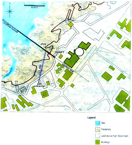
Fig. 2. Location of Shaft

Fig. 3. Groundwater Flow Conditions during Pumping from the Shaft
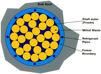
Fig. 4. Freezing of Shaft & Milling out of Waste

Fig. 5. Wet Retrieval of Shaft Waste
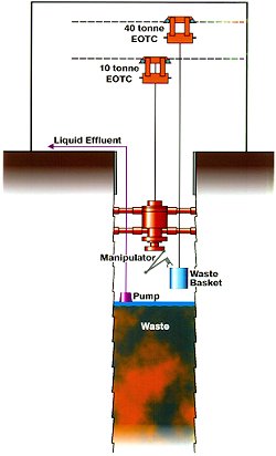
Fig. 6. Dry Retrieval of Shaft Waste

Fig. 7. Present Groundwater Flow Conditions
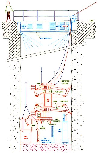
Fig 8. Robotic Platform Inside Shaft for Waste Retrieval
Fig. 9. Reception & Separation of Waste Areas Inside Waste Treatment Plant.

Fig. 10. Alternative Freezing Option where Waste Remains Unfrozen.