
DESCRIPTION, SAFETY DESIGN CRITERIA AND COLD
COMMISSIONING OF THE STORAGE FACILITY FOR
HLW AND MLW IN BELGIUM
G. Nuyt, J. Van Averbeke, and J.L. Catoire
BELGATOM
J.P. Boyazis and M. Demarche
ONDRAF/NIRAS
ABSTRACT
"The multipurpose storage facility located in Mol is designed to store different types of radioactive waste, resulting mainly from the reprocessing by COGEMA of spent fuel from Belgian nuclear power plants.
The building is of modular design, so the total capacity can be extended easily.
In the first phase, the modules will store conditioned radioactive waste from the reprocessing of 630 T of spent fuel, corresponding to about five years operation of the Belgian nuclear power stations. Two different modules are built. Construction of the first, intended to store 100 m3 of vitrified high-level waste in canisters, was completed in 1994; the second, intended to store 1100 m3 of other type of waste packages, was completed in 1997"
PURPOSE OF THE FACILITY
The HLW Storage is a multipurpose facility located in Mot-Dessel, on BELGO-PROCESS site, designed to store different types of radioactive waste, resulting mainly from the reprocessing (by COGEMA in La Hague, France) of spent fuel from Belgian nuclear power plants.
The Building is of modular design, so the total capacity can be extended easily.
In the first phase, the capacity of the storage modules will store conditioned radioactive waste from the reprocessing of 630 T of spent fuel, corresponding to about five years operation of the Belgian nuclear power stations. Two different modules are planned. Construction of the first, intended to store 100 m3 of vitrified high-level waste in canisters, was completed in 1994; the second, intended to store 1100 m3 of other type of waste packages, was completed in 1997.
The building is ready since 1996 to receive the first vitrified high-level waste canisters.
DESCRIPTION OF THE WASTE PACKAGES
The different types of waste packages resulting from reprocessing are:
SAFETY DESIGN CRITERIA
Radiation and Contamination
The building is divided in different radiation areas according to the maximum activity present and the occupational time by the operators in the areas.
Dose rate for the operators is limited to 50 mSv/year. Contact dose rate for the external walls of the building is limited to 0.002 mSv/h. Dose rate at the outskirts of the BELGO-PROCESS site is limited to 0.5 mSv/year for the population.
To satisfy these criteria, convenient shielding has been placed around the sources by considering their maximum activities and conservative operating conditions.
To ensure the protection against contamination, the building has been designed completely watertight (foundations, walls and roof). To prevent and detect any contamination at the exhaust ventilation stack, a filtering and a continuous monitoring of the air is foreseen.
Furthermore, the ventilation systems of the storage cells have been designed to maintain the temperature of the packages, the equipment and the concrete walls of the cells within acceptable limits under normal and accidental conditions and to control the progressive depression levels in accordance with the potentially contaminated zones.
Criticality
The risk of criticity for the glass containers storage cells has been demonstrated to be negligible under any operating conditions.
Beside these safety criteria, other criteria taking into account accidental conditions have been considered for the design of the building:
The fire protection is ensured by appropriate detectors and manual/automatic extinguishers;
To reinforce the protection of the essential equipment, fire areas have been defined to reduce the risk of propagation of a fire.
To protect the building against an external fire, a strip of 15 meters around the building is free of any combustible material.
The risk of an explosion due to a build-up of hydrogen in the drums storage halls has been found negligible.
The building has been designed according to the reference earthquake of the BELGOPROCESS site (acceleration of 0.1 g, during 8 seconds for the "near-field" spectrum and acceleration of 0.025 g during 20 seconds for the "far-field" spectrum).
The integrity of the areas containing the radioactive wastes in maintained during and after an earthquake, to prevent releases in the atmosphere.
Furthermore, some equipment has also been designed to keep its integrity and in some cases, to be still operable during and after an earthquake.
In particular, the cooling of the glass containers remains possible after an earthquake by the seismically qualified exhaust circuit of the storage cells.
The walls of the critical areas (unloading cell, storage cells and transfer halls) of the building have been designed to withstand an impact of a military airplane (F16 fighter) crashing at a speed of 150 m/s.
Some critical equipment, such as the unloading cell cranes and the loading machine for the glass containers, has been designed to withstand the earthquake induced by the airplane impact.
The critical areas of the building are built above he general underground water level of the site.
The building and the exhaust ventilation stack are designed to withstand to the maximum wind velocity in accordance with the Belgian regulations.
In case of a loss of electrical supply, the essential equipment of ventilation is fed by an automatically started diesel-generator. Would this diesel not start, another diesel would then feed the extraction fans of the glass containers storage cells. Moreover, the storage cells can be cooled by a natural convection circuit.
Safety devices are provided to prevent mishandling of the waste packages.
Electrical interlocks (e.g., between trolleys and doors) are installed to prevent potentially hazardous situations.
The fall of a transport cask can only happen in the reception hall: to limit the consequences of this fall on the structures of the critical areas, the foundations of the reception hall are separated from the rest of the building.
To limit the consequences of a fall of a waste package in the unloading cell, following features have been added:
To reduce the risk of a fall of a glass container during its handling by the loading machine, special attention was given to the design of the grab and a shock-absorber is installed at the bottom of each pit.
GENERAL DESCRIPTION
Building
The building is divided in 6 parts (figures 1, 2 and 3).

Figure 1

Figure 2

Figure 3
The reception hall is designed to receive the transport cask conveyed to the site on a special trailer.
The unloading cell is equipped to open the transport casks, unload the primary packages and transfer them to their storage cell. Checking of the primary packages is also possible. The cell is also designed for the loading of the transport casks with waste packages removed from the storage cells for transport to the final repository site.
The transfer hall is equipped with a loading machine covering the storage cells for glass containers.
The storage cell for glass containers consists of 60 pits. Each pit can accommodate up to 10 containers giving a present local capacity of 600 containers.
Each storage hall for drums (HLW and MLW packages) is designed to contain up to 270 HLW cement drums, 2042 MLW bitumen drums and 99 alpha MLW cement drums, total 1100 m3 of waste.
The building is designed to add in the future up to 10 modules of drums.
Handling
The reception hall is equipped with a 1300 kN crane [J] designed to lift the transport casks and puts it down on a transfer motor-operated trolley running on rails.
The trolley transport the cask between the reception hall and the unloading cell through an air-lock.
The unloading cell is equipped with:
Each equipment of the unloading cell is operated from the control room [10].
The transfer hall is equipped with the loading machine [H] attached to a crane (see figure 4).
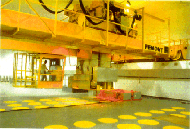
Figure 4
The loading machine is designed to transfer the glass containers between the unloading cell and the storage pits in a shielded hood.
The shielding of the machine provides protection against gamma radiation and neutrons.
This machine is locally controlled by an operator travelling on the crane.
MAIN STEPS OF THE COLD COMMISSIONING PROCEDURE
General Schedule
The general schedule of the project is given in attached figure 5.
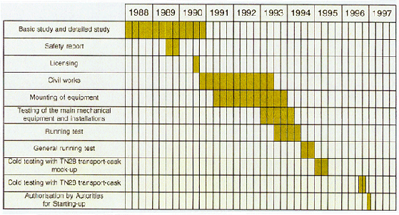
Figure 5. General Schedule of "Building 136"
The storage facility for high-level waste (the glass canisters) has been under construction since August 1990 and hot commissioning is foreseen at the beginning of 1998. The other parts of the building, for storage of MLW and HLW, have been under construction since 1993 and hot commissioning is foreseen at the end of 1998.
Cold Testing with a Mock-Up Transport Cask
To simulate the transport, handling and unloading of a transport cask, a mock-up transport cask from COGEMA, has been used. The mock-up has the same characteristics - dimensions and weight - as the real transport cask TN28.
Tests with the mock-up began in January 1995 and took 4 months.
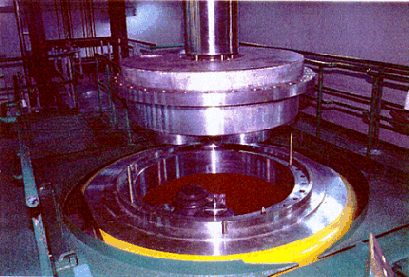
Figure 6
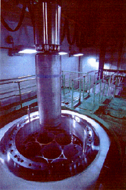
Figure 7
Cold Testing with the Transport Cask TN28VT (September-October 1996)
Before reception of a hot transport cask, another campaign using a TN28 transport cask (see figure 8) has been executed to verify all the improvements made, and to check special tools and devices which were not tested in the first campaign.
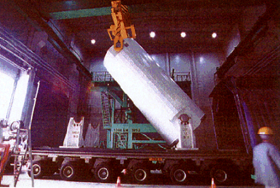
Figure 8
This testing phase has permitted to complete the first phase of the test.
All the previous tests have been executed once again, but moreover some particular tests which were not practicable with the mock-up have been performed:
Conclusions
Simulations carried out with the mock-up and TN28 cask and glass canister have made possible to adapt or optimise all the handling operations, and have provided the operators with valuable experience.
The multipurpose facility for interim storage is now ready to receive the waste packages.