HYDROGEN DIFFUSIVITY THROUGH DRUM AND
LINER VENTING FILTERS
Terry Wickland
Nuclear Filter Technology, Inc.
John Schierloh
Safe Sites of Colorado, RFETS
ABSTRACT
The hydrogen diffusion rate through different types of drum venting filters and snap fit bag venting filters. The filters are used by contractors throughout the DOE complex for ventilation of hydrogen from confinement layers. The data provided herein is of critical importance as refinements to packaging configurations are proposed and approval of the NRC is sought. The nuclear waste generators and shippers wish to maximize the amount of plutonium packaged in each drum which is limited by the G value, or wattage limit. A critical path to increasing the amount of waste material packaged in a drum is to take credit for the increased hydrogen transport capabilities of improved filter vents. If credit may be taken for efficient hydrogen transport of improved filter vents, then fewer drums are required, and a significant cost savings is realized.
The diffusion rate through a NucFil-013 3/4" filter is 8.27 E-06 mole/second/mole fraction (M/S/M Frac.), which is about 2.1 times the minimum for a standard waste box or over 4 times greater than that required for a drum filter. The NucFil-016 filter allows hydrogen gas to diffuse at about 8 times the minimum rate established for a waste box at 31.6 E-06 M/S/Mole fraction.
The most widely used NucFil-030 snap-fit bag style bag filter diffuses hydrogen at 10.8 E-06 M/S/M Frac. A larger size carbon-carbon bag filter diffuses hydrogen at about 23.28 E-06 M/S/M Frac.
BACKGROUND
Rocky Flats Environmental Technology Site (RFETS) has an inventory of several thousand drums of TRU waste which are to be shipped to WIPP. Many of these drums are currently ‘wattage-limited’, which means that the amount of fissile material in the drum exceeds the amount that is theoretically capable of producing a flammable quantity of hydrogen during shipment. The buildup of hydrogen in the drum is a result of both the rate which it is generated and the resistance to diffusion from the drum. The drum wattage limits are based on both theoretical worst case generation rate and worst case diffusion resistance. Currently, a method has been developed at RFETS to perform real-time hydrogen generation rate measurements. This paper presents a method to perform real-time hydrogen diffusion measurements for drum and bag filters. Knowledge of actual diffusion resistance values for specific filter types would support the effort to increase wattage limits for waste types that are currently restricted to low amounts of fissile material per drum.
It is estimated that use of actual measured filter diffusion resistance (as opposed to the current worst-case values) in the equations used in the determination of watt limits could result in a 2X – 3X overall increase in the amount of fissile material allowed per drum. For RFETS this represents a reduction of several thousand drums required to be repackaged and shipped. Similar savings can be realized at several other DOE sites, leading to increased storage efficiency at WIPP.
PROCEDURE
The schematic diagram on the following page (Fig. 1) shows the test set up. A certified mixture of hydrogen gas and nitrogen is circulated by a peristaltic pump through the gas chromatograph and returned to the test vessel. A photograph of the hydrogen diffusion test stand is shown in Figure-2 below. At the start of a test and at five minute intervals, a sample of the gas is injected into the detector for analysis. Seven samples are take over a 35 minute period. The amount of hydrogen in the test vessel decays over time due to diffusion through the filter. The hydrogen diffusivity losses through tubing and connections are well known and results are adjusted accordingly.

Figure 1

Figure 2. Hydrogen Diffusion Test Stand used in Testing the Filters
The chromatogram peak area is related to the amount of hydrogen in the container. The decay rate, or hydrogen diffusivity , D, through the assembly is given by:
D = PV/t RT Ln(Ho/Ht)
where P is atmospheric pressure, V is the volume of the vessel with connective tubing, t is elapsed time in seconds, R is the Ideal Gas Constant, and T is the temperature in Kelvin. The diffusion rate, D, is in Moles/Second / Mole Fraction (M/S/ M Frac). The initial concentration of hydrogen given by the chromatogram peak area is Ho and the amount of hydrogen after time t is Ht.
The diffusion tests are conducted at the Nuclear Filter Technology Laboratory in Golden Colorado which is at an elevation of 6000 feet. Therefore P, the atmospheric pressure is adjusted down from 1 atmosphere to 0.81 atmospheres. The volume of the test container was measured by recording injected water volume until the vessel was full. The volume of the test vessel is 4910 milliliters. The ideal gas constant is 0.08206 L-Atm / Mol-Kelvin. The tests were conducted in a temperature controlled room and was maintained at between 22 and 27 degrees centigrade. Barometric pressure was monitored occasionally but is not a variable in the spreadsheet calculations of the diffusion rate.
Peak area data is transferred to a spreadsheet where the diffusion coefficient is calculated at each data point. An average of six diffusion coefficients is taken and reported as the diffusion rate, D’. The standard deviation of the mean is also calculated and reported as a result.
EQUIPMENT AND OPERATING PARAMETERS
The gas chromatography used for the tests is a Shimadzu GC 14A with a 6 port "Event 91" valve. The detector is a thermal conductivity detector (TCD) and the column is a MS-5 A, 2.5 meter 80 X 100 molecular seive. Operating parameters of the GC are 100 C detector temperature, 110 C column and injector temperature, and 150 C TCD temperature. The current across the TCD is set at 75 milliamps. The data acquisition software used is Shimadzu EzChrome.
QUALITY ASSURANCE
The gas chromatography tests for hydrogen gas were conducted in accordance with DOE/WIPP Procedure 520.1 "Gas chromatography Determination Of Hydrogen And Methane in Waste Container Headspace" which is based on ASTM Method 1946-82. The key Quality Assurance elements derived from Procedure 520.1 and applied to the test described here are the use of National Institute of Standards and Technology (NIST) traceable standard gases for establishing a three point calibration curve. Calibration curves were run at the start of each day that tests were conducted. The minimum detection limit (MDL) of the thermal conductivity detector was measured in accordance with 40 CFR Pt. 136, app. B. The chromatograph peak area was measured 14 times in response to the certified hydrogen gas concentration of 1.5% hydrogen. The MDL is estimated at 230 parts per million.
FILTERS TESTED
Table-I below shows the filter models tested, indicates whether the filter is a drum bung vent (used for ventilation of newly generated waste), drum ventilation and purge filter (filters used for drum ventilation and installed by a machine where gas sampling of an existing waste drum is required), or a bag filter (for ventilation of waste bags). One other manufacturer’s drum vent filter was tested, the UltraTeck Model 94001. The table also provides a brief physical description of the filter housing such as size and material type, lists the filter media type (carbon-bonded-carbon or sintered stainless steel) and gives performance criteria for flow and aerosol removal efficiency of each filter. Each filter tested was randomly selected from work in process inventory and tested as is. Only five filters of each filter type were selected for testing because the time required for each hydrogen diffusivity test is so long.
In order to establish a standard diffusion rate for comparison of future measurements taken at other laboratories, the diffusion coefficient through a 1/8" diameter hole in a 16 gage steel plate was measured.
Table I. Description of Filters Tested
|
FILTER MODEL |
FILTER MEDIA |
VENT TYPE |
HOUSING DESCRIPTION |
@ 1" W.C. DP AVERAGE FLOW RATE |
AEROSOL REMOVAL EFFICIENCY |
|
UT94001 |
sintered steel layers |
drum / bung vent |
3/4" 304 SS w/ 1/16" side holes |
200 ml/min |
>99.97% |
|
NucFil-012 |
carbon / carbon |
drum / bung vent |
3/4" mild steel ‘vise grip’ w/ 1/8" hole |
200 ml/min |
>99.97 % |
|
NucFil-013 |
carbon / carbon |
drum / bung vent |
3/4" 304 SS ‘vise grip’, w/ 3/8" hole |
200 ml/min |
>99.97 % |
|
NucFil-013 SS |
sintered steel |
drum / bung vent |
3/4" 304 SS ‘vise grip’, w/ 3/8" hole |
200 ml/min |
>99.97 % |
|
NucFil-013 G |
carbon / carbon |
drum / bung vent |
3/4" 304 ss, w/ Gore-Tex Membrane |
200 ml/min |
>99.97 % |
|
NucFil-016 |
carbon / carbon |
drum / bung vent |
2" 304 SS ‘vise grip’ w/ 1" hole |
1000 ml/min |
>99.97 % |
|
|
|
|
|
|
|
|
NucFil-073-01 |
carbon / carbon |
drum vent and purge |
3/8" self tapping, 6 holes, ##" long |
200 ml/min |
>99.97 % |
|
NucFil-073-08 |
carbon / carbon |
drum vent and purge |
3/8" self tapping, 6 holes, ##" long |
200 ml/min |
>99.97 % |
|
NucFil-074 SS |
sintered steel |
drum vent and purge |
7/16"or 9/16" self tapping, 1 hole |
200 ml/min |
>99.97 % |
|
NucFil-072-SS |
sintered steel |
drum vent and purge |
3/8" self tapping, 2 holes, ##" long |
200 ml/min |
>99.97 % |
|
|
|
|
|
|
|
|
NucFil-030 |
carbon / carbon |
bag vent filter |
1" diameter PE snap-fit |
200 ml/min |
>99.97 % |
|
NucFIl-032 |
carbon / carbon |
bag vent fitler |
1.5" diameter PE snap-fit |
400 ml/min |
>99.97 % |
|
NucFil-034 |
electricly charged |
bag vent / volume reduction |
1.5" diameter PS snap-fit w/ ring |
800 ml/min |
>99.97 % |
|
|
|
|
|
|
|
|
NucFil-PBVC-1 |
membrane |
Bottle vent for liguids |
1" Nalgene cap |
Water Entry Pressure = 20 PSI |
|
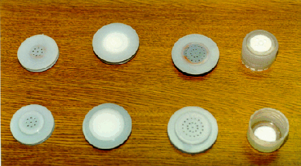
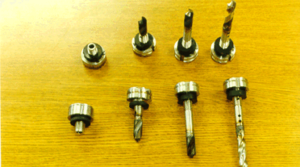
Figures -3, 4 and 5 show photographs of each filter model that was tested. Figure-3 shows the Drum Vent Filters (DVFs) including the UltraTeck 94001, NucFil-012, Nucfil-013, NucFil-013 SSS, and NucFil-016. Figure-4 shows bag venting filters including the NucFil-030, NucFil-034, NucFil-032, and the NucFil-PBVC-1 (bottle vent cap). Figure -5 shows the drum vent and purge filters including the NucFil-074 SSS, NucFil-072 SSS, NucFil-073-01 and NucFil-073-08. The NucFil-073-08 is an improved version of the -073-01 version. The vent hole positions were adjusted slightly in order to improve hydrogen gas transport.

Figure 3. Drum Vent Filters (DVFs)

Figure 4. Bag Vent Filters

Figure 5. Drum Vent and Purge Filters
DIFFUSION TEST RESULTS
The diffusion test results for the different types of filters are given in Table-II below. Shown is the filter model, average diffusion rate, standard deviation of test results, the related R value or equivalent Resistance value, and the test population. The R value is calculated by multiplying 0.0138586 by the inverse of the diffusion rate.
Table II. H2 Diffusion Rates of all Filters with Equivalent Resistance Value
|
MODEL |
AVERAGE DIFFUSION RATE |
STNDRD. DEVATN. |
RESISTANCE R VALUE |
TEST POP. |
|
WIPP SAR MIN DRUM1 |
1.9 |
|
7294 |
|
|
NucFil-072 SSS |
2.48 |
0.12 |
5588 |
5 |
|
NucFil-0122 |
2.66 |
0.60 |
5214 |
5 |
|
UT94001 |
2.68 |
0.34 |
5165 |
5 |
|
NucFil-074 SSS |
2.91 |
0.18 |
4767 |
5 |
|
NucFil-073-01 |
3.61 |
0.54 |
3836 |
5 |
|
WIPP SAR MIN SWB |
3.70 |
|
3746 |
|
|
NucFil-073-08 |
3.83 |
0.37 |
3614 |
5 |
|
1/8" hole in 16 gage |
4.76 |
0.10 |
2914 |
4 |
|
NucFil-PBVC-1 |
6.38 |
0.92 |
2172 |
3 |
|
NucFil-013 GoreTex |
7.98 |
0.24 |
1737 |
5 |
|
NucFil-013 |
8.28 |
0.42 |
1675 |
5 |
|
NucFil-030 |
10.06 |
2.10 |
1378 |
5 |
|
NucFil-013 SSS |
12.45 |
0.54 |
1113 |
5 |
|
NucFil-034 |
17.93 |
0.65 |
773 |
5 |
|
NucFil-032 |
23.28 |
1.46 |
595 |
5 |
|
NucFil-016 |
32.79 |
2.27 |
423 |
5 |
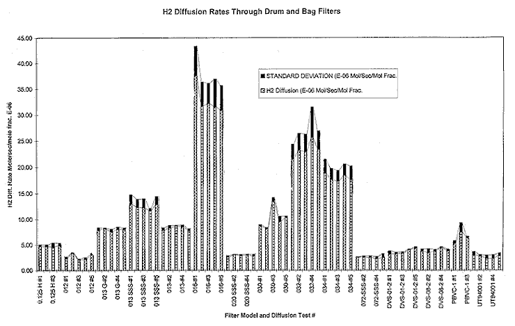
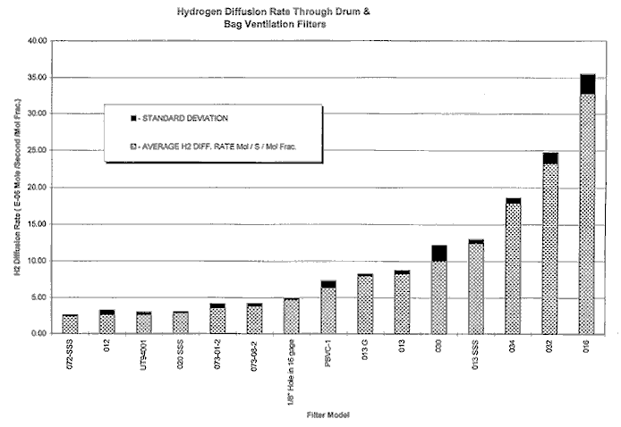
Figure -6 below shows the individual hydrogen diffusion coefficients measured for each test filter. Figure -7 is a bar graph where each bar represents the average hydrogen diffusion coefficient for each filter model/type. Complete data, over 120 pages, is available upon request.

Figure 6. Hydrogen Diffusion Coefficients Measured for each Filter
H2 Diffusion Rates Through Drum and Bag Filters

Figure 7. Average Hydrogen Diffusion Coefficients Measured for each Filter Model
Hydrogen Diffusion Rate Through Drum & Bag Ventilation Filters
COMPARISON TO PREVIOUS STUDIES
There have been at least four informative papers written on the hydrogen diffusion coefficients through various NucFil drum vent filters. For example, Peterson3 tested the NucFil-012 drum vent filters which have 1/8" hole in the lid and the bottom of the filter. From Peterson’s study, a group mean of 2.3 E-06 M/S/M Frac. was measured. On one single filter, a value of 1.9 E-06 M/S/M Frac. was measured which later became the standard minimum diffusion rate.
In a second study by Peterson4 the NucFil-013 G (with Gore Tex laminate) and the NucFil-030 snap-fit bag filter were measured for hydrogen diffusivity. The average hydrogen diffusivity for the Nucfil-013 G was measured at 5.9 E-06 M/S/Mole Frac. with a standard deviation of about 0.345. The hydrogen diffusivity of the NucFil-030 bag filter were measured at an average of 4.26 E-06 M/S/M Frac. and a standard deviation of 0.112.
David Hobbs5 of Westinghouse Savannah River Site measured the diffusion rate through the NucFil-013 at 4.315 E-06 M/S/ M Frac.
In a report from Los Alamos National Laboratory, "Hydrogen Diffusion Coefficient for Drum and Bag Filters" conducted by CSL-1, the Nucfil-013 and NucFil-030 were measured for hydrogen diffusivity. The Nucfil-013 hydrogen diffusion coefficient was measured at 8.5 E-06, and the Nucfil-030 was measured at 11.1 E-06 M/S/M Frac.
Table-III below summarizes test results from this study, and compares the results with others that have been done.
Table III. Comparison of Hydrogen Diffusion Rates With Other Studies
(E-06 Mol/s/Mole Frac.)
|
|
012 |
013 |
013 G |
030 |
|
CURRENT STUDY - 1998 |
2.65 |
8.27 |
7.98 |
10.06 |
|
LANL - 1993 |
- |
8.5 |
- |
11.1 |
|
HOBBS - 1990 |
- |
4.31 |
- |
- |
|
PETERSON #2 - 1990(?) |
- |
- |
5.9 |
4.26 |
|
PETERSON #1 - 1988 |
2.3 |
- |
- |
- |
Table III demonstrates that the hydrogen diffusion measurements conducted in this test correspond well with results done previously. Since about 1992 significant improvements in filter design have led to increased hydrogen diffusion rates.
SUMMARY
The WIPP TRUPACT II minimum hydrogen diffusion rate for a drum filter is 1.9 E-06 M/S/ M Frac. The WIPP TRUPACT II minimum hydrogen diffusion rate for a standard waste box is 3.7 E-06 M/S/M Frac. At this time, calculating the G value of the waste stored in a drum only allows credit for the above mentioned hydrogen diffusion rates. By allowing credit to be taken for much higher diffusivity rates, far fewer drums, perhaps by a factor of 2, will required.
The diffusion rate through a NucFil-013 3/4" filter is about 8.27 E-06 M/S/M Frac., which is about 2.23 times the minimum for a standard waste box or over 4 times greater than that required for a drum filter. The NucFil-016 filter allows hydrogen gas to diffuse at about 8 times the minimum rate established for a standard waste box at 32.8 E-06 M/S/M Frac..
The most widely used NucFil-030 snap-fit bag style bag filter diffuses hydrogen at 10.6 E-06 M/S/M Frac. A larger size carbon-carbon bag filter diffuses hydrogen at about 23 E-06 M/S/M Frac.
Using actual hydrogen diffusion resistance coefficients measured in this study, as opposed to worst case values, in equations used in the determination of watt limits, a 2X to 3X overall increase in the amount of fissile material allowed per drum will result. If this practice is adopted DOE wide, similar savings can be realized at several other DOE sites, leading to increased storage efficiency at WIPP.
FOOTNOTES
1
TRUPACT II SARP Section 1.3.52
The NucFil-012 filter is no longer produced and was tested for comparison to results with Peterson.3
Determination of Hydrogen Flow and Diffusion Properties of Selected Graphite Filters, S.H. Peterson, July 20, 1988, Westinghouse Research & Development Center, Pittsburgh, PA, PO 94-WRS-25880-ID4
Determination of Flow and Hydrogen Diffusion Characteristics of Carbon Composite Filters at The Waste Isolation Piolet Plant, S.H. Peterson, E.E. Smeltzer, and R.D. Straw, Chemical and Process Development Department, Westinghouse, Pittsburgh, PA.5
Measurement of the Hydrogen Transport Characteristics of Transuranic Waste Filter Vents, David Hopps, November 20, 1990, Westinghouse Savannah River Company, WSRC-TR-90-492