
SEALING OF THE SHAFTS OF A REPOSITORY IN CLAY
G. Volckaert, F.-X. Holvoet, F. Bernier, M. Put
SCK•CEN
Boeretang 200, B-2400 Mol, Belgium
ABSTRACT
One of the main assets of clay as a host rock for the disposal of radioactive waste is that all contaminant transport is dominated by diffusion. Due to the low hydraulic conductivity of clay the contribution of advection to the transport is negligible. However the access shafts of the disposal installation may act as preferential pathways for radionuclide migration and create circumstances in which advective transport becomes important. Therefore first a literature study and performance assessment calculations were performed with the aim to derive quantitative functional requirements for the shaft seals and secondly a large scale in situ demonstration project was started.
INTRODUCTION
In the case of the Boom Clay studied as a potential host rock for high level radioactive waste by SCK•CEN at Mol, Belgium, the clay layer is situated below a 180 m thick major aquifer with which the shaft could form a direct connection with the disposed waste. Therefore the shafts have to be properly sealed.
First a desk study was launched to determine quantitative functional requirements for the shaft seals and the sealing material. The results of this desk study including the results of the assessment of the consequences of a poor sealing scenario are briefly explained.
Secondly an overview is given of a demonstration project, called RESEAL, that has been started in 1996 in the framework of the EC R&D programme on "Management and storage of radioactive waste (1994-1998)". More detailed information on the in situ borehole sealing experiment and on the design of the large scale shaft sealing test is given.
Finally the main conclusions of both studies are drawn-up.
FUNCTIONAL REQUIREMENTS FOR A SHAFT SEAL
Literature Study
The most cited basic objective of repository sealing is the restoration of the capability of the geological barrier to assure long-term waste isolation (Nowak 1989, Van Sambeek 1993, Engelmann 1989, Santiago 1995, Svemar 1995, Akiyoshi 1995). Some add for the shafts the objective of prevention of human intrusion (Santiago 1995, Svemar 1995).
The functional requirement for the shaft seals mentioned in the first place is the hydraulic conductivity which should preferably be such to restore the initial hydraulic conditions. In its Technical Reports Series No. 319 "Sealing of underground repositories for radioactive waste" (IAEA 1990) the IAEA formulates the seal performance objectives as follows:
"The overall objective of penetration sealing is to restore the viability of the formation affected by the penetration to assure long term isolation of waste radionuclides. An ideal goal of repository sealing activities is to leave ground water circulation within and in the vicinity of the disposal formation exactly as it was before site exploration and development. It follows logically that sealed shafts, tunnels and boreholes should have the same hydraulic conductivities as the geological materials through which they pass."
In this statement the IAEA represents an ideal case and states that one needs to consider to what extent this requirement is practicable. In low permeability host rocks, the goal of restoring the original hydraulic conditions may be completely impossible to reach. In particular, the excavation disturbed zone may retain a somewhat enhanced hydraulic conductivity regardless of the remedial techniques used. In practice a higher permeability can be acceptable if performance assessment calculations show that the dose or risk criteria for repository performance are still fulfilled. This appoach is also suported by the IAEA.
The sealing of the EDZ (Excavation Disturbed Zone) is considered as an essential functional requirement for the shaft seals. Another important functional requirement given by most authors is that the seal has to withstand the maximum expected gas and water pressures at the repository depth. The shaft seal has to be able to resist the stress induced by the convergence of the host rock.
For the sealing material a long lifetime is required, but no minimal value was put forward in the literature. From the indications found in the studies mentioned above, we have derived a minimum lifetime between a few thousand years up to about 100000 years. Such lifetimes require a good chemical stability and compatibility with the host rock.
In most studies only qualitative statements as given above are
mentioned and no quantitative requirements are given. Only in the case of the WIPP site
quantitative requirements for the shaft seals are defined (Van Sambeek 1993). In this case
a seal hydraulic conductivity of 10-12 m/s
to 10-13 m/s was required.
In three studies performance assessments have been made concerning the influence of shaft seals on the long term safety (Stormont 1984, Akiyoshi 1995, Marivoet 1997). Stormont (1984) has shown that for the WIPP site the performance assessment of a poor shaft sealing scenario only infers minimal functional requirements. The performance study of PNC (Akiyoshi et al., 1995) shows that in a diffusion dominated case the shaft sealing has only a minor influence on the radionuclide transport. In the case of the Mol site (Marivoet 1997) the assessment of a poor sealing scenario has shown that this conclusion is only valid if the distance between the shaft and the disposal galleries is at least equal to the thickness of the clay (i.e., about 100 m). For shorter connection galleries additional calculations show that an overall hydraulic conductivity for the shaft of 3 10-10 m/s is maybe sufficient. Geomechanical modelling studies have shown that the use of a strongly swelling clay for a shaft seal allows to reconsolidate the Boom Clay and to increase the radial stresses in the EDZ, however the original stress tensor cannot be restored. These studies have also shown that the shaft construction procedure and techniques in a plastic clay can have an important effect on the later seal performance and on the sealing of the EDZ. On the other hand in situ tests such as the shaft seal test at STRIPA (Pusch et al., 1987) have shown that very low permeabilities (10-11 m/s to10-13 m/s ) can be achieved quite easily.
The assessment of a poor sealing scenario for the Mol site is explained in more detail in the next chapter.
The Poor Sealing Scenario in the Case of the Mol Site
In the frame of the long-term performance studies, consequence analyses for altered evolution scenarios are performed. Marivoet (1997) performed a consequence analyses for the so called poor sealing scenario. In this scenario it is supposed that the sealing of the shaft and transport gallery has failed so that they might form a preferential pathway for radionuclide migration. The hydraulic conductivity of the transport gallery and shaft backfilling material is supposed to be a thousand times larger than that of the surrounding host rock i.e. 2 10-9 m/s versus 10-12 m/s. The radionuclide retardation factors for the filling material were chosen three times smaller than that of the host rock clay. To increase the potential impact of the scenario, they assumed that the hydraulic gradient over the clay layer is upwards (+0.04) while the present-day gradient is downwards (-0.02). In this case it might happen that the disposal gallery functions as a large filter, which collects water from the clay formation, and that might cause a vertical convective flow through the access shaft. The hydraulic gradient of 0.04 is the maximum positive gradient calculated by J. Patyn (1987) in his geoprospective study.
Fig. 1. Poor Sealing Scenario: Scheme of the Considered Repository Configuration
To simplify the calculation, a vertical 2D cross-section was simulated. The scheme of the considered repository configuration is shown in Fig. 1. The PORFLOW (Runchal 1994) finite volume code was used to perform the calculations. The calculations were performed for C-14, Cs-135, U-236, Np-237 and Pu-242 to have a good spread in half-life times (i.e. C-14: 5730 y, Cs-135: 2.3 106 y, U-236: 2.34 107 y, Np-237: 2.14 106 y and Pu-242: 3.76 105 y) and retardation coefficients, and also to test the potentially most sensitive nuclides. The consequences, i.e., the total radionuclide flux at the clay-aquifer interface, of the poor sealing scenario were compared with those of the normal evolution scenario with the same inverse gradient, called the "reference". The comparison shows that for most radionuclides there is no or a weak increase in the radionuclide flux at the interface. In Fig. 2 the fluxes of Np-237 for the two scenarios are given. Only in the case of Pu-242 there is an increase with more than a factor 1000 though the absolute value of the Pu-242 flux remains negligible, i.e., lower than 10-13 Bq/y. The bulk of the radionuclides is still diffusing into the host layer as it is the case in the normal evolution scenario and only a small fraction migrates via the "preferential pathway", which consists of the poorly sealed transport gallery and access shaft. In the case of Pu-242 the fraction that diffuses into the host rock decays practically completely before it reaches the aquifer, while a small quantity of the fraction that migrates via the access gallery and shaft reaches the aquifer. The latter is due to the assumed lower retention of Pu-242 in the access gallery and shaft in combination with its half-life of 3.76 105 years. For the other radionuclides the fraction, which migrates through the clay host rock, largely reaches the aquifer because they are very long lived or almost not retarded (e.g. C-14).
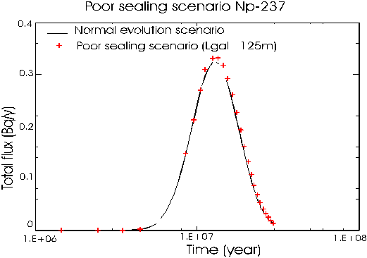
Fig. 2. Comparison of the Np-237 fluxes at the clay-aquifer interface for the normal evolution and poor sealing scenarios.
The vertical pathway through the host clay layer between the waste repository and the aquifer (i.e., 45 m) is shorter than the pathway that follows the access gallery and the shaft (i.e., 125 m + 45 m). Therefore, Marivoet (1997) also studied the influence of the length of the access gallery on the poor sealing scenario for the case of Np-237. They found that for an access gallery with a length of 60 m and 30 m the maximum Np-237 flux increased with respectively a factor 42 and 1000 in comparison with the flux calculated for the 125 m long access gallery. This effect is due to the lower retention in the access gallery and shaft and not due to the higher permeability. This shows that the repository design can have an important influence on the requirements for the sealing. This effect could also occur with other radionuclides. However as this effect is caused by a combination of three main parameters i.e., retardation, pathlength and half-life, it is difficult to make a priori predictions for other radionuclides.
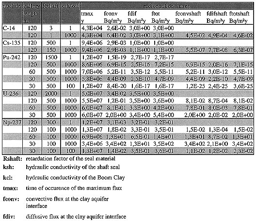
To study further the influence of the length of the transport gallery and the permeability it was decided to perform, also for the other four considered radionuclides, calculations for a connection gallery length of 60 m and 30 m and for a hydraulic conductivity of the filling material only 100 times lower than that of the host rock (Volckaert 1996). The results of these calculations are summarized in Table 1. In this table not only the maximum flux at the clay aquifer interface and its time of occurrence are given but also the contribution of the convective and diffusive flux to the total flux and the convective, diffusive and total flux at the clay aquifer interface at the location of the shaft only. For C-14 the maximum influence of the gallery length on the flux at the clay aquifer interface is less than 15% and can thus be neglected. For Cs-135 the length of the connection does not influence the total flux at the clay aquifer interface. In this case the flux through the shaft is in all cases negligible compared to the total flux at the clay aquifer interface. In the case of U-236 for a 30 m long connection gallery the total flux is 50 % higher than for the case of a 120m long connection gallery. This increase is due to the convective transport in the shaft. For Pu-242 the total radionuclide flux increases with about a factor 106 for a 30 m long transport gallery, though this flux is still very small and its consequent dose remains negligible.
For Pu-242 the total flux is equal to the flux through the shaft, which is dominated by the convective transport. Np-237 behaves in the same way as Pu-242, but the maximum flux increase is a factor 104, which is in this case not negligible.
Table 1 clearly shows that in the reference case the convective flux is at least a factor hundred lower than the diffusive flux, while in the poorly sealed shaft the convective flux is about one to two orders of magnitude larger than the diffusive flux. This is due to the local higher Darcy velocity in the shaft compared to the clay host rock. To study the influence of the seal permeability on the radionuclide fluxes, additional calculations were performed for Pu-242 and Np-237 using a 100 times larger hydraulic conductivity in the connection gallery and shaft than in the clay host rock instead of a 1000 times larger hydraulic conductivity. The results given in Table 1 show clearly a strong reduction of the radionuclide flux through the shaft which has become smaller than the total flux. In these latter cases the convective and diffusive flux through the shaft were of the same order of magnitude. This means that an overall (i.e., including the excavation damaged zone) hydraulic conductivity for the connection gallery and shaft of 3 10-10 m/s is sufficient to reduce the influence of the shaft on the radionuclide fluxes to a negligible level, even if the shaft is located close to the disposal galleries and the sealing material has a low sorption capacity. Calculations for all critical radionuclides might be required to show the general validity of this conclusion.
In the RESEAL project the capacity of bentonite plugs to seal a borehole and a shaft with its excavation damaged zone will be tested in situ.
Table I Results of the Poor Sealing Scenario Assessment
THE RESEAL PROJECT
Overview of the RESEAL Project
The objectives of the RESEAL project are the following:
The RESEAL project includes a borehole sealing test, a large scale shaft sealing test and the required supporting laboratory experiments and modelling studies.
The Borehole Sealing Experiment
This in situ test consists in the sealing of a (250 mm diameter, 15 m long) horizontal borehole drilled in the Boom clay from the HADES underground research facility at Mol, Belgium. Two different sealing materials will be tested. For this experiment, the sealing plugs will consists of precompacted clay blocks. The first plug will be made of FoCa clay and the second of Serrata clay respectively the French and the Spanisch reference sealing materials. Both materials are Ca-bentonites.
Figure 3 gives a general view of the experimental set-up. It consist of two compartments designed to test the sealing materials. The two compartments each contain a central tube with filters and total stress transducers. The lateral faces of the compartment consist of circular filters containing total stress transducers. The different positions of the total stress sensors gives the opportunity to measure the radial and the longitudinal stresses in the seal plugs. The main aim of the lateral filters is to test the borehole sealing by water and gas injections. The central filters are used to artificially saturate the seal plugs because natural hydration by the clay host rock could take more than one year. Each filter is equipped with a separate chamber. Those chambers are connected by 2 standpipes: one is connected to a pressure transducer, the other is foreseen for the water or gas injection. Close to the seal compartment, the piezometer is also instrumented with filters and total stress transducers. The instrumentation allows to measure the evolution of the porewater pressure and the total stress in the host rock and the sealing plugs.
The sealing plugs are constructed from precompacted bentonite blocks. These blocks have been compacted to a dry density of 1.7 g/cm3 for the FoCa clay and 1.65 g/cm3 for the Serrata clay. With these dry densities, the clay plugs will - once saturated - generate a swelling pressure of 4.4 MPa, which corresponds with the in situ lithostatic stress. Their hydraulic conductivity in saturated state will be about 10-13 m/s.
The experiment has been installed in November 1997 and the seal plugs have been saturated in the first trimester of 1998. The hydraulic and gas tests on the seals will be performed in the 2nd and 3rd trimester of 1998.
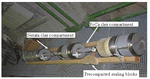
Fig. 3 : General view of the borehole sealing test.
The large scale shaft sealing test
This experiment consits in the sealing of the experimental shaft (see Fig. 4) in the Hades underground laboratory at SCK•CEN. This 24 m deep shaft with at the bottom and 8.5 m long gallery was constructed in 1984 to test the possibility to make underground constructions in a plastic clay at 200 m depth without using the freezing technique. The internal diameter of the shaft is 1.4 m and it is lined with 30 cm thick conical concrete blocks. The experimental gallery and lower part of the shaft will be backfilled with concrete. The seal will be installed above this concrete backfill between 15 m and 17 m depth in the experimental shaft. At the level of the seal, the concrete liner and about 10 cm of the host clay will be removed. Above the seal an anchored concrete plug will be installed, to take up the swelling pressure of the seal. The clay seal will consist of a mixture of high density (> 2 g/cm3) FoCa clay pellets mixed with FoCa clay powder in such a ratio that the mean density will be about 1.7 g/cm3. At full saturation this mixture will generate a swelling pressure of about 4.4 MPa.
Sensors will be embedded at three levels in the seal for measuring water content, suction, porewater pressure, displacement and total stress in the three principal directions. The central filter will be used to saturate the seal artificially, that will take about one year.
The host rock will be instrumented with three one meter long priezometers and three displacement transducers installed radial to the shaft axis. They will be installed in two planes with a 120º angle between each instrument. A vertical piezometer will be installed parallel to the shaft axis. All piezometers will be equipped with independent filters and total stress sensors. This in situ instrumentation will be able to measure the longitudinal, radial and tangential stress and the porewater pressure distribution around the seal.
The aim of the seal and host rock instrumentation is to measure the hydromechanical behavior during the hydration and testing of the seal and to validate hydromechanical codes used for blind predictions of the seal behavior.
The host rock instrumentation has been installed in the first trimester of 1998 to allow sufficient time for equilibration. The seal will be installed in the last trimester of 1998 and will be hydrated in 1999. The hydraulic and gas testing of the seal is planned for the year 2000.
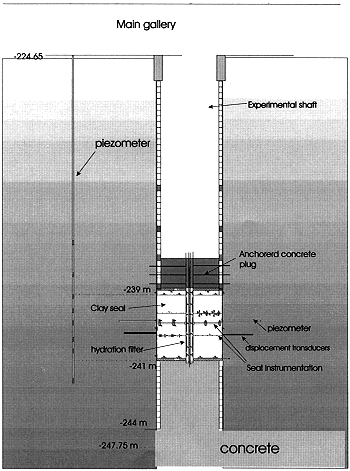
Fig. 4. Design of the shaft seal test.
CONCLUSIONS
The main aim of repository sealing is the restoring of the initial hydraulic conditions in the host rock. The design and layout of a repository in a clay layer can strongly influence the minimal functional requirements of a shaft seal. For a well designed repository, a higher hydraulic conductivity of the shaft seal than of the clay host rock may be acceptable. The shaft construction procedure and techniques in a plastic clay can have an important effect on the later seal performance. The sealing of a borehole in a plastic clay is currently being tested in situ. The installation of a shaft seal using a granular swelling clay material and with removal of the shaft lining will be demonstrated in situ on a representative scale.
ACKNOWLEDGEMENT
The RESEAL project is a joint project between SCK$CEN (coordinator) and ANDRA (main subcontractor: CEA) and ENRESA (main subcontractors: CIEMAT, UPC). The project is financially supported by EC, ANDRA, ENRESA and NIRAS/ONDRAF.
REFERENCES