REVIEW OF PROCESS SAFETY ISSUES RELEVANT TO
VITRIFICATION OF RADIOACTIVE WASTES
Vijay Jain and Roberto T. Pabalan
Center for Nuclear Waste Regulatory Analyses
Southwest Research Institute
San Antonio, Texas 78238
ABSTRACT
The current plan for privatization of the Hanford tank radioactive waste treatment and immobilization operations comprises a proof-of-concept or demonstration phase (Phase I) and a full-scale operations phase (Phase II), during which a smooth transition in regulatory oversight from the U.S. Department of Energy (DOE) to the U.S. Nuclear Regulatory Commission (NRC) is planned. This paper discusses potential process safety issues that could be encountered during vitrification of Hanford radioactive wastes based on information derived from operations of existing facilities. Such information will be useful for evaluating safety assessments of Hanford solidification plants and in developing an appropriate regulatory program for radioactive waste immobilization/solidification operations.
INTRODUCTION
The DOE established the Tank Waste Remediation System (TWRS) program at the Hanford site in 1991 to manage the maintenance and cleanup of radioactive wastes contained in 177 aging underground storage tanks. The DOE is implementing the Hanford Federal Facilities Agreement and Consent Order of 1989 [1] (the Tri-Party Agreement), and remediate the waste. To meet the requirements of the Tri-Party Agreement, the DOE is in the process of privatizing the waste treatment and immobilization operations. The TWRS privatization is divided into two phases, a proof-of-concept or demonstration phase (Phase I) and a full-scale operations phase (Phase II). A Memorandum of Understanding [2] has been established between the DOE and the NRC for Phase I activities. This memorandum enables the NRC to acquire sufficient knowledge of the physical and operational situation at the Hanford waste tanks and of the processes, technology, and hazards involved in Phase I activities to (I) assist the DOE in performing reviews in a manner consistent with the NRC regulatory approach, and (ii) be prepared to develop an effective regulatory program for the possible licensing of DOE contractor-owned and contractor-operated facilities during Phase II.
The NRC regulatory program will focus on appropriate aspects of operational safety and health risks to the public, the workers, and the environment. Information from High-Level Waste (HLW) vitrification experience at existing facilities, such as those at the West Valley Demonstration Project (WVDP, West Valley, New York), Defense Waste Processing Facility (DWPF, Savannah River Site (SRS), Aiken, South Carolina), Tokai Vitrification Facility (TVF, Japan), Sellafield (United Kingdom), Mayak Vitrification Plant (Russia), Waste Vitrification Plant (WVP, India), and the Marcoule and La Hague vitrification facilities in France, has been gathered for use in the development of the regulatory framework for the privatized Hanford facility. This paper will discuss potential process safety issues that could be encountered during the processing of Hanford wastes based on information derived from operations of existing facilities. Key processing considerations related to operational safety and health risks, broadly classified into four categories, are reviewed in this paper. These categories are: (I) tank farms and feed preparation, (ii) waste solidification and storage, (iii) offgas treatment and release, and (iv) remote handling and human factors. The significance of process parameters in each category are discussed.
TANK FARMS AND FEED PREPARATION
The radioactive wastes stored at the Hanford site are complex mixtures of solids and liquids, incompletely characterized, consisting of liquids, slurries, saltcakes, and sludges. More than 99 percent of the waste volume and a majority of the total radionuclide inventory are contained in 149 single-shell tanks (SSTs) and 28 double-shell tanks (DSTs). Summary descriptions of the wastes in SSTs and DSTs are provided in reports by Gephart and Lundgren [3] and Cragnolino et al. [4], and a detailed assessment of tank waste contents is provided by Agnew [5].
The total volume of SST waste is approximately 132 million liters, of which 66 percent is wet saltcake consisting of crystallized nitrate and other salts, and 34 percent is sludge consisting of solids formed after waste neutralization with sodium hydroxide addition. The solids and dissolved constituents of the SSTs are ~90 percent sodium nitrates and nitrites, with the remainder consisting mostly of phosphates, carbonates, hydroxides, and sulfates. Radioactivity in the SSTs is dominated by Sr-90 (75 percent) and Cs-137 (24 percent); Sr is mostly in the sludge, whereas Cs is chiefly in the saltcake and interstitial liquids. The DST waste, with an approximate total volume of 76 million liters, is dominated by supernatant liquids transferred from SSTs and, thus, is 85 volume percent water. The constituents of the DST waste, like those of the SSTs, are dominated by sodium nitrate and nitrite (~70 percent), with ~20 percent metal hydroxides and the rest as phosphates, carbonates, oxides, and sulfates. The DST waste radioactivity is 72 percent from Cs-137, which is mostly in the slurry and interstitial liquid, and 27 percent from Sr-90, which is mostly in the sludge.
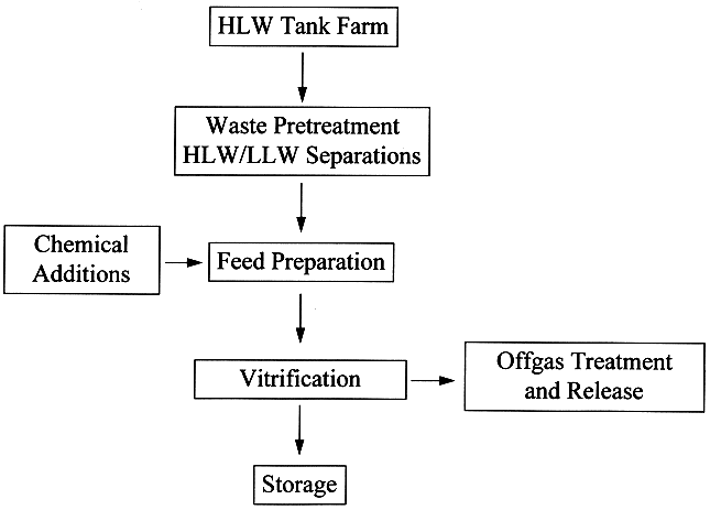
The storage of wastes at the Hanford site poses safety hazards such as generation and combustion of flammable gases [6] such as hydrogen or ammonia in the tanks, energetic reactions between organics and nitrates/nitrites [7] that could release radioactivity to the environment, and high heat loads from radionuclide decay [8] that could damage waste tank concrete structure. These issues are unique to the TWRS and are being evaluated independent of the TWRS privatization program. In addition, several tanks that have potential for onsite or offsite radiation exposure to workers through uncontrolled release of fission products have been identified as watch list tanks in accordance with Public Law 101-510, Section 3137, "Safety Measures for Waste Tanks at Hanford Nuclear Reservation" [9] to ensure safety of the tanks is maintained during storage. The following discussion focuses on safety issues related to waste retrieval, transfer, homogenization, pretreatment, feed preparation, and reductant addition. Fig. 1 shows a general schematic of waste processing for vitrification.
Waste Transfer Lines
Several safety issues are of potential concern during mixing and transfer of TWRS wastes. The foremost concern is rupture of transfer lines resulting from changes in waste slurry rheology. Depending on rheological behavior, the waste could become either more fluid or more viscous during mixing or transfer. High viscosity causes a potential for transfer line plugging that could result in accumulation of flammable, radiolytically produced gases such as hydrogen. A rise in flammable gas concentration in a plugged transfer line above the lower flammability limit (LFL) increases the probability of explosion, particularly in the presence of air or nitrous oxide in the waste. In a transfer line containing waste with high heat load due to radioactive decay of Sr-90 and Cs-137, plugging could result in a severe temperature excursion and problems such as thermal expansion and distortion or rupture of the line. Analogous problems could arise from waste that has a potential for energetic or exothermic reactions due to organic oxidation mechanisms.
Waste Transfer and Mixing
Precipitation of specific components, exothermic reactions, rheological changes, and flammable gas generation due to mixing of different wastes potentially could damage the mixing and transfer pumps. A transfer of waste to an empty tank poses no process safety hazard provided the tank material is compatible with the waste characteristics. For example, at the WVDP, a highly acidic THOREX waste was transferred to a carbon-steel tank containing an alkaline PUREX washed sludge. Prior to transfer, laboratory tests using both simulated and actual waste, coupled with fluid flow modeling to study mixing behavior, were conducted and a plan was developed to ensure proper tank safety during transfer [10]. A detailed analysis of waste compatibility prior to waste transfer should address potential problems and incidents relating to incompatibility of wastes and tank material.
Fig. 1. Generic Process Flowsheet for Waste Treatment and Vitrification
Waste Homogeneity
Waste homogeneity during mixing and transfer is another important safety issue. While criticality is not an issue for the Hanford Site HLW tanks [11], potential for the accumulation of fissile material should be addressed during normal processing campaigns. The potential for criticality resulting from preferential segregation of fissile material or from failure of mixing pumps should be addressed before the retrieval and transfer of tank contents is initiated. In addition, waste inhomogeneities could result in waste batches that are unacceptable for processing, leading to production of nonconforming waste forms or to the return of these batches to the tank farm. Although production of nonconforming waste forms is not in itself a safety hazard, excessive concentrations of minor components, such as sulfates and phosphates, could result in increased corrosion of melter components, and accumulation of noble metals could cause formation of a conductive sludge on the melter floor and electrical shorting of the melter.
Waste Pretreatment
Waste pretreatment is an important part of the solidification process. Pretreatment allows separation of highly radioactive species, such as Sr-90, Tc-99, Cs-137, and transuranics (TRU), from the supernatant. Understanding the chemistry of the wastes and the separations media helps ensure a safe pretreatment process. Each component of the waste, before pretreatment to extract radionuclides, should be compatible with the pretreatment media. For example, in the WVDP pretreatment process, Pu solubility in the supernatant was found to increase due to dilution of the waste in the waste tank with time. This increase in Pu solubility resulted in Pu being released with the effluent into the evaporator [12]. Another example is the evolution of benzene during the In-Tank Precipitation (ITP) process at the SRS facility which uses tetraphenyl borate (TPB) to precipitate Cs as Cesium TPB. This is a safety issue and currently is being addressed by the DOE as a result of the safety assessment of the ITP process by the Defense Nuclear Facilities Safety Board (DNFSB) [13].
Feed Preparation for Solidification
The feed preparation flowsheet, like the pretreatment flowsheet, should provide a safe operating environment. Each component of the glass-forming chemicals, before it is mixed with waste, should be compatible with waste. Chemicals added other than in an established sequence could result in temperature excursions due to exothermic heat of reaction, agglomeration, or the release of NOx. As an example, in the WVDP flowsheet the addition of a polyglycol-based antifoam agent after nitric acid addition results in NOx fumes and, therefore, it is added last to minimize NOx generation [14]. In addition, the WVDP process flowsheet requires an acidic feed to ensure that proper rheology is maintained during mixing and feeding to a melter. When acidic glass formers are added to an alkaline waste, the rheology of the mix changes very rapidly. The mix rheology exhibits a maximum in slurry viscosity between a pH of 6 and 8 and decreases at lower or higher pH. Detailed laboratory studies on rheological behavior as a function of pH allowed the WVDP to prepare feed batches within processable bounds. In the DWPF feed preparation flowsheet, adjustments are made using frit and formic acid [15]. The DWPF frit is much more erosive than the chemicals used at the WVDP, which has resulted in erosion of the DWPF feed tank components [16]. These examples highlight the importance of using the proper chemicals to ensure that the design life of the components is attained. Other potential safety issues related to the feed preparation process include erosion and corrosion of on-line instruments that could result in the malfunction of on-line pressure, temperature, and level instruments. For example, erosion of level measurement tips could lead to erroneous reading and could result in overfill or underfill of the feed preparation tanks. Measures to mitigate the above problems will help minimize any remote or hands-on maintenance work that need to be done.
Selection of Reducing Agents
One of the major concerns in selecting a feed preparation flowsheet is the selection of reducing agents and a proper understanding of noble metal-catalyzed reactions. For example, if a formic acid-based flowsheet is selected for TWRS waste (similar to the DWPF flowsheet), the potential for hydrogen generation due to catalyzed decomposition of formic acid by noble metals should be addressed to ensure hydrogen generation does not exceed the LFL. In addition, noble metal-catalyzed formic acid reduction of nitrite and/or nitrate to ammonia is a significant safety concern because of ammonium nitrate formation, which is an explosion hazard [17]. For the TWRS waste feed preparation flowsheet, the effects of organics and organometallic compounds that are introduced from the waste should also be addressed to ensure that they do not result in formation of hazardous compounds.
WASTE SOLIDIFICATION AND STORAGE
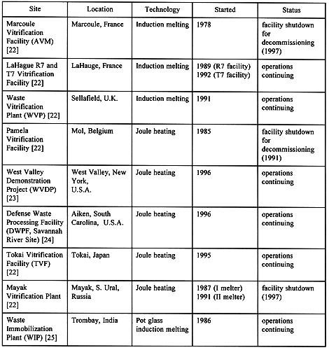
Initial research on the development of vitrification processes for HLW started in the early 1960s. Since then, vitrification has gained wide acceptance as a viable technology for solidification and disposal of HLWs stored around the world, and has also been recommended for disposal of low-level radioactive wastes (LLWs) and mixed low-level radioactive wastes in the United States. Table I shows the status of HLW vitrification plants around the world.
Table I. Status of HLW Vitrification Plants
In a typical HLW vitrification process, waste is mixed with glass-forming chemicals and the resultant mixture is melted at temperatures greater than 1,100 ° C in a melter inside a shielded cell. The melting process fuses the various components of the mixture into a monolithic glass melt that is poured into and casted in stainless steel canisters. Since the operation of the first HLW vitrification plant at Marcoule, no catastrophic accident involving HLW vitrification technology, (i.e., accidents that resulted in any significant radioactive dose to the public or release to the environment) has occurred. This does not mean that vitrification technology is free from problems and issues that could result in failures. In fact, over the past 20 years, several operational incidents, such as a breach of a melter vessel allowing molten glass to leak/drop out of the melter, an uncontrolled release of offgas from the melter, failure of the joule-heating system, or plugging of the glass pour drain, have occurred at various HLW melter operations and LLW test melters. The following are examples of melter failure incidents:
These examples clearly indicate that an in-depth understanding of melter design and of compatibility between melter and waste components is extremely important to minimize melter incidents. Even though the melter incidents that have occurred to date have not resulted in deaths or injuries, they did pose a threat to worker health and safety. In a robustly designed and built melter, control of the waste and glass chemistry under defined melter temperature and pressure ranges is a key to safe operations. Parameters such as chemical reactions, redox control, formation of conductive sludges, and glass properties such as viscosity, phase separation, and liquidous temperature should be addressed for safe operations. These parameters are discussed in the following sections.
Chemical Reactions
In a typical waste vitrification process, as slurry is fed to a melter, water evaporates and leaves behind a crusty layer of waste and glass-forming components. Organic and inorganic salts present in the slurry decompose in the crusty layer, releasing oxides of nitrogen, carbon, and sulfur. These reaction gases along with water vapor, exit the melter through an offgas port. Knowledge of possible exothermic and endothermic chemical reactions that could occur within the crusty layer and of formation of reaction gases such as ammonia, cyanides, and aromatic hydrocarbons, is necessary to ensure that the process does not exceed safe concentration levels.
Glass Redox
The control of redox, defined as reduction-oxidation potential of the melt, is probably the most important process control parameter in the melter. The redox is depends on both feed and melting systems, and is a result of the combined effects of reducing agents such as organics, oxidizing agents such as nitrates and nitrites; the waste concentrations of transition metal ions such as Fe, Cu, Mn, Ni, and Cr; and melter operating conditions such as bubbler flow rates, melter temperature, pressure, and air-in-leakage into the melter. Both bubblers and air-in-leakage introduce extra oxygen in the system and, could potentially shift redox equilibrium. A redox response within a specified range is necessary to avoid process upsets that eventually could lead to permanent melter damage.
Because iron is abundant in most wastes, the redox response in most waste vitrification systems is measured by analyzing the Fe2+/Fe3+ ratio. The melter is defined as extremely reducing if the Fe2+/Fe3+ ratio is greater than 1. Under such conditions, sufficient accumulation of conductive metals and metal sulfides could short-circuit the melter. If the Fe2+/Fe3+ ratio is less than 0.01, the melter is defined as extremely oxidizing. The quantitative lower limit of Fe2+/Fe3+ is not known; existing redox measurement equipment cannot analyze Fe2+/Fe3+ less than 0.01 with confidence. Under extreme oxidizing conditions, foaming is observed in the melter. Foam creates an insulating layer of gas bubbles between the cold-cap and the melt, disrupting the thermal gradients in the melter. Typically, foaming, if controlled at its onset, slows the glass production rate and, in most cases, is not an issue. However, if foaming is not controlled, conditions can arise that could lead to melter shutdown. For instance, the foam could fill the melter plenum, cause the melter offgas line to plug, and eventually pressurize the melter. If the melter pressure exceeds the pressure differential needed for glass pouring, a sudden uncontrolled discharge of the melt will occur. The discharge could result in complete blockage of the discharge chute with solid glass and lead to thermal shock of the melter due to a sudden loss of thermal mass in the melt chamber.
Because no on-line redox measurement tools are available, the redox response is usually forecast based on some empirical relationship between the feed characteristics and melter response. The WVDP and the DWPF use empirical models to forecast the redox state of the glass melt based on measured concentrations of the reducing and oxidizing components of the feed. The empirical models were developed based on extensive laboratory and pilot scale testing of simulated feeds. At the WVDP, the redox is controlled by addition of sugar to the feed, the amount of which is based on the nitrates, total organic carbon, and percent total solids in the waste [29]. At the DWPF, the redox is controlled by addition of either formic acid or nitric acid to the feed using an empirical relationship based on the nitrate and formate analysis [15]. Both the WVDP and DWPF melters operate at oxidizing conditions to avoid the formation of conductive sludges.
Redox monitoring of wastes containing high concentrations of MnO2 and CuO is much more complex. Since both MnO2 and CuO transitions occur at the oxidizing end of the Fe2+/Fe3+ couple, the redox response cannot be correlated to the Fe2+/Fe3+ ratio. In addition, reboiling occurs under oxidizing conditions. Reboiling is attributed to the shift in the redox state of the melt with a shift in temperature. The higher the temperature, the more reducing the melt becomes. Under reboiling conditions, MnO2 is reduced to MnO, releasing significant amounts of oxygen. The reboil event behaves similarly to foaming, but is dependant on temperature changes in the melter.
The sensitivity of the redox response as a function of reductant concentration is extremely important in defining the redox range for any melter system. An acceptable range for redox response in the DWPF system is limited by the presence of CuO in the DWPF waste. In the melter, CuO could precipitate as Cu metal at moderately reducing conditions (e.g., at Fe2+/Fe3+ greater than 0.5). On the other hand, an acceptable range for redox response in the WVDP system is very sensitive to the presence of nitrites. The operating range for redox is limited by the amount of nitrites present in the WVDP feed. Both DWPF and WVDP operations are limited to an extremely narrow redox range. The situation for TWRS waste is much more complex due to the presence of significant amounts of different types of organics. Melter incidents resulting from redox control problems for the TWRS waste should be addressed to determine the key parameters that will control the redox response.
Conductive Sludges and Noble Metals
Conductive sludges in the melter are defined as precipiated conductive metal sulfides or metals in the glass melt and are formed under reducing conditions. In addition, noble metals such as Rh, Pd and Ru, because of their very limited solubility in glass, tend to settle on the melter floor, forming highly electrically conductive paths. Most of these metals cannot be easily pretreated or extracted. Both formation of conductive sludges and settling of noble metals could potentially result in electrical shorting of a joule-heated melter. Thus, processing of noble metals through the melter likely would be a major safety issue for TWRS waste.
The melter design and feed composition should address the risk of premature melter failure, such as the one that occurred at the Pamela melter, due either to settling of noble metals. An example of these studies is the extensive testing that was done at the Pacific Northwest National Laboratory to determine the impact of noble metals on the operational life of a reference Hanford Waste Vitrification Plant melter [18].
Glass Properties
The proper design of glass composition is important to ensure that the glass is processable within the operating range of the melter and would not impact the melter design life. The glass properties that dictate glass processing include glass viscosity, electrical resistivity, liquidous temperature, and phase separation. These properties are discussed in the following sections.
Viscosity
Control of glass viscosity, similar to control of waste rheology, is extremely important for continuous and safe melter operations. HLW glass melters operate between a viscosity of 20 and 100 poise at their operating temperatures. The convective currents in the melt, due to the thermal gradients in the melter, are responsible for homogenization of waste and glass-forming chemicals. At a viscosity higher than 100 poise homogenization of the waste components is delayed because higher viscosity slows down kinetics of the convective mixing. In addition, high viscosity makes the flow of glass from the melter into the canister slow and difficult. Also, an extremely high viscosity could result in the formation of a glass plug at the discharge section. On the other hand, a viscosity less than 20 poise results in an increased volatilization of radioactive components, such as Tc-99 and Cs-137, and of alkali oxides, such as Na2O, Li2O, and K2O and boron oxide. This could result in accumulation of radionuclides in the offgas filters instead of encapsulating in glass. The filters may need frequent replacement to avoid plugging. In addition, low glass viscosity increases refractory erosion.
Electrical Resistivity
The control of electrical resistivity of the glass melt is extremely important for joule-heated melter operations. The electrical resistivity is mostly due to ionic conductivity and is a function of glass composition, largely the concentrations of alkali oxides such as Na2O, Li2O, and K2O. Joule-heated HLW glass melters operate at electrical resistivities between 5 and 10 ohm-cm at melter operating temperatures. High resistivity of the glass melt results in high voltage potential across the electrodes that allows conduction to occur within the refractory walls that could cause dissipation of heat in refractory walls and increase power requirements. On the other hand, low resistivity of the glass melt results in high current density that could exceed the current carrying capacity of the electrodes required to maintain the melt at the desired temperature and, thus, result in electrode failure.
Liquidous Temperature
Whenever a glass melt is cooled below the liquidous temperature, crystal formation occurs in the melt. The crystals that are formed could settle on the melter floor as do noble metals. However, unlike noble metals, the crystals may not be conductive. If the melter is maintained below the liquidous temperature for an extended period of time, these crystals could continue to form and eventually block the glass pour drains and make the melter non-functional. Depending upon the nature of these crystals, they may or may not redissolve in the melt upon reheating to above liquidous temperatures.
Phase Separation
Phase separation occurs whenever a component exceeds its solubility limit in the glass melt. The glass melts have very limited solubility for components such as noble metals and sulfur. The issues related to noble metals have been discussed in a previous section. The issues related to sulfur solubility are discussed next.
At the WVDP, the sludge was washed several times to reduce the concentration of sulfates, measured as SO3, below 0.25 weight percent. The SO3 solubility in WVDP reference glass is 0.25 weight percent; SO3 concentrations above this value may result in formation of an immiscible molten sulfate (gall) layer on top of the cold-cap. This gall behaves like a foam. Also, at the Pamela vitrification facility, the amount of waste that could be processed into the glass was limited by the amount of sulfur in the waste [21]. In addition, the sulfates, in the presence of chlorides in the waste, dramatically corrode stainless steel and Inconelâ between 500 and 900 ° C. Glass composition should address the phase separation issues during melting. Potential for molten sulfate formation in Hanford waste is discussed in a paper by Sullivan [30].
OFFGAS TREATMENT AND RELEASE
There are two major functions of the offgas treatment system: first, to ensure that offgas released to the atmosphere meets local, state, and federal guidelines, and second, to maintain a negative pressure in the vitrification facility. A typical offgas exiting the melter contains water vapor and oxides of nitrogen, carbon, and sulfur, along with entrained feed particles and volatile components. As the offgas is cooled, the entrained feed particles and volatile components deposit along the offgas pipeline. A robust design allows the entrained particles to either drop right into the melter or be carried over into another vessel without depositing along the offgas pipeline. If the design is not capable of meeting functional requirements, the deposits eventually build up, blocking the offgas flow. Under such conditions, the offgas released from the cold cap in the melter will pressurize the melting chamber. If the melter pressure exceeds the pressure differential needed for glass pouring, a sudden uncontrolled discharge of the melt similar to foaming events could occur. The discharge could result in a complete blocking of the discharge chamber with solid glass that would cause thermal shock of the melter due to a sudden loss of thermal mass in the melt chamber. In addition, overpressurization may cause the melter to release offgas outside the cell.
A generic offgas treatment consists of a quencher to cool the offgas, a series of scrubbers to remove entrained particles, a High-Efficiency Mist Eliminator (HEME) for removing mist, and High-Efficiency Particulate Air (HEPA) filters for containment of radioactive particulates. In addition, the offgas system could include specific treatment components depending upon the nature of the offgas.
In most vitrification facilities, the offgas system controls the pressure in all the feed vessels and the melter. A slightly negative pressure is required to contain radioactivity within the system. Failure of the offgas blower or process upsets, such as foaming, plugging of offgas lines, or plugging of the glass discharge chamber, could disrupt the offgas pressure control. During such upsets, it is likely that certain parts of the system could go slightly positive and release radioactivity outside the cell.
REMOTE OPERATIONS AND HUMAN FACTORS
In a HLW vitrification facility, all process components and equipment are enclosed within heavily shielded concrete walls due to the highly radioactive environment. A large amount of equipment is operated and maintained using master slave manipulators (MSMs) and in-cell cranes. The complexity of the in-cell layout of equipment requires long hours of expert MSM and in-cell crane operators. Human factors are, therefore, an integral part of safe operations. Designing low-maintenance, MSM-friendly equipment and training operators to efficiently and effectively operate the MSMs will significantly reduce human errors, such as misalignments of pipes and hoses and incomplete closure of valves, that could lead to offgas releases or slurry leaks. Training of operators using mock-ups would also reduce downtime and incidents involving human error. An example of the use of MSM-friendly equipment is the redesign of a slurry sample station at the WVDP to simplify valve operations. This redesign reduced the sampling time and minimized radioactive slurry drips on the sample station floor [31]. Similarly, at the WVP at Sellafield, improvements to in-cell cranes and MSMs alleviated most of the in-cell operating problems and dramatically reduced downtime [32].
CONCLUSION
A consideration of process safety issues relevant to solidification of radioactive wastes is important to ensure that any proposed TWRS privatized waste solidification facility poses minimum risk to the workers, the public, and the environment. HLW vitrification technology has been successfully used worldwide to encapsulate highly radioactive wastes, and operations of existing facilities provide important information on process safety issues that may be relevant to the TWRS program. Some of these safety issues are reviewed in this paper, but future assessments of these safety issues with respect to a TWRS facility need to be based on the specific characteristics of the Hanford wastes and designs of the treatment process.
ACKNOWLEDGMENT
The work was performed by the Center for Nuclear Waste Regulatory Analyses (CNWRA) for the Nuclear Regulatory Commission (NRC), Office of Nuclear Material Safety and Safeguards, Division of Fuel Cycle Safety and Safeguards, under Contract No. NRC-02-97-009. This paper is an independent product of the CNWRA and does not necessarily reflect the views or regulatory position of the NRC.
REFERENCES