
IN-SITU INVESTIGATIONS ON SEALING OF EMPLACEMENT DRIFTS AND BOREHOLES FOR HEAT GENERATING HIGH-LEVEL WASTE
J. Droste, T. Rothfuchs, K. Wieczorek
GRS-Fachbereich Endlagersicherheitsforschung
Theodor-Heuss-Strasse 4
D-38122 Braunschweig
S. Heusermann
Federal Institute for Geosciences and Natural Resources (BGR)
Stilleweg 2
D-30655 Hannover
W. Bechthold
Forschungszentrum Karlsruhe GMBH
Projektträger des BMBF für Entsorgung
Postfach 36 40
D-76021 Karlsruhe
ABSTRACT
Experiments are being performed in the Asse salt mine in Germany to study the sealing capacity of backfill and host rock in a deep geologic salt repository and to provide a basis for further refinement and validation of numerical codes required for the prediction of long-term repository performance. The experiments investigate different disposal concepts for heat generating radioactive waste which were developed for a repository in a salt dome. The paper presents a description of the projects and summarizes the results from several years of experiment performance.
INTRODUCTION
The work described in this paper is related to two emplacement concepts for heat generating radioactive waste (Bechthold et al., 1997).
In these concepts the functions of the backfill are to
Crushed salt was decided to be the most suitable backfill material. As a consequence of rock salt convergence, its permeability decreases continuously to very small values which are almost equal to the undisturbed rock. Furthermore, the mechanical behavior of the salt grains is similar to the surrounding rock salt. Therefore, crushed salt provides a continuously increasing resistance to drift closure and a relatively homogeneous stress distribution around drifts and boreholes. According to the present planning, the material for drift backfilling will consist of crushed salt that remained from the excavation works, i.e., a coarse material with a maximum grain size of 60 mm. The material for backfilling boreholes will be fine-grained crushed salt with a 10-mm maximum grain size.
For sealing emplacement panels, bulkheads will be constructed in the access drifts. Their function is to isolate the waste disposed of in the emplacement areas and to prevent brine from intruding into these areas during the time period in which the backfill is still a pathway for fluids in the repository. The effectiveness of the bulkheads will depend on the permeability of the excavation disturbed zone (EDZ) in the host rock around the drifts.
In order to investigate these phenomena, three in situ tests are carried out in the Asse salt mine. They were designed to simulate reference repository conditions of the emplacement concepts described above. Their purpose is to expand the understanding of backfill and rock behavior which earlier had been gained primarily from laboratory investigations. In these in situ experiments the combined effects of heat, convergence, rock pressure, and backfill compaction are being studied. The experimental results are used to refine and qualify the numerical models and to evaluate their capability to predict the performance of a repository over long time periods.
DRIFT EMPLACEMENT: THE TSS TEST
The objective of the Thermal Simulation of Drift Storage (TSS) test is to study the backfill behavior in emplacement drifts and to improve relevant computer codes and constitutive equations required for predictive calculations. According to the drift emplacement design, the Pollux casks will be deposited in 3.5-m-high and 4.5-m-wide drifts. The initial porosity of the crushed salt backfill will be about 35%. Therefore, its sealing capacity will be low in the beginning. As a consequence of host rock convergence, however, the backfill will be compacted until its permeability is almost equal to the surrounding rock salt. This process which is influenced by temperature, thermal conduction, rock convergence, and rock pressure has to be predicted for long time periods in repository performance assessments. The relevant models have to be calibrated and their predictive capability has to be evaluated.
The experiment is carried out in a test field consisting of two backfilled drifts and several observation and access drifts. In each test drift three electrically heated containers were deposited. The dimensions of the test drifts and the simulated casks as well as their heat power are as outlined above in the drift emplacement concept (Fig. 1).

Fig. 1. Layout of the TSS experiment in the Asse salt mine
Measurements are carried out on
The measuring instruments are placed on the heater casks, in the backfill, and in the surrounding rock. Measurements are conducted in the heated area around the heater casks as well as in the non-heated regions farther away from the casks where the influence of heating is less significant (Droste et al., 1996). The test is operational since September 1990. Heating was at a constant power output of 6400 W / Pollux cask or 19200 W / drift. In the following, some characteristic results of the measurements are presented.
At the surface of the casks a maximum temperature of 210°C was reached after five months. Because of the increasing thermal conductivity of the backfill during its compaction, the temperature subsequently decreased to 165 - 175°C at the moment (Fig. 2). Short-term irregularities in the temperature decrease were due to malfunctions of the heater power control system. At the drift floor the temperature has currently reached 125°C (Fig. 2). Temperatures of up to 100°C are recorded at the drift walls and up to 92°C at the roof above the casks. In a depth of 0.3 m below the heaters temperatures of 145°C are measured, decreasing to 107°C in 1.2 m depth. Between the heated drifts temperatures are reaching 81°C in the pillar centre. In the almost non-heated area 12 m away from the heaters the temperatures have increased up to 47°C in the meantime. Actually, the temperatures predicted by thermal model calculations agree very well with the measurements (Pudewills, 1997).

Fig. 2. Drift temperatures around a central heater and at the heater surface
With the start of heating, a significant acceleration of the drift closure rate was observed. Within three months, the rates increased by a factor of 8 to 10 compared to the non-heated sections of the test drifts (Fig. 3). Because of the increasing rigidity of the compacted backfill, the rates have been reduced again subsequently. Present rates in vertical direction amount to 0.6 %/a, whereas horizontal rates of 0.45 %/a are recorded. These values are still twice as much as before heating. In the non-heated area the drift closure increased gradually, currently reaching 0.5 %/a and 0.3 %/a in vertical and horizontal direction, respectively. Calculated drift closure rates in the non-heated sections show a rather good agreement with in situ measurements. In the heated area, however, the closure rates are overestimated by the calculation by about 40% (Korthaus, 1991). This may be caused by the modeling of the test geometry, the chosen values of the material parameters of rock salt and backfill, the constitutive equations describing the backfill compaction, and the assumed initial stress state in the test field.

Fig. 3. Horizontal and vertical drift closure in the heated and the non-heated area
As a result of drift closure, the initial backfill porosity of about 35 % has been reduced to 25 - 26 % in the heated area up to now. Because of the slow drift closure rates, the observed backfill compaction is also sigificantly lower than predicted (Fig. 4). The actual porosity in the non-heated sections ranges between 31 % and 32.5 %.
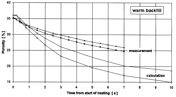
Fig. 4. Predicted and measured backfill porosity in the heated area
To determine the initial stress state in the test field, stress measurements using the overcoring method have been carried out. The measured data indicate a reduced stress state of 12 MPa in vertical and of 10 MPa in horizontal direction. These values are significantly lower than the expected lithostatic rock mass pressure of 18 MPa. The influence of 130 excavations in the Asse mine remaining from salt mining between 1908 and 1964 is obvious. Hence, the reduced stress state must be taken into account in model calculations.
To observe the thermally induced stress change in the host rock, about 50 stress monitoring stations with Glötzl-type hydraulic stress gauges have been installed in the test field. Different set-ups with 4, 7 or 8 components with different orientations are being used. The stations have been installed in the roof, the walls, and the floor of the drifts as well as in the pillar at different distances to the heater casks.
In most measurement directions a significant increase of stress was observed a short time after excavation of the test drifts. Subsequently, a decrease of stress due to creep and stress relaxation of the host rock was measured. With the start-up of heating in September 1990, the stresses increased again reaching a maximum after some weeks but then decreased continuously. Since 1994, a quasi steady state is observed around the test drifts. Because of the ongoing heat dissipation, however, an increase of stress is still being observed at farther distances north and south of the test field.
The increasing backfill compaction is creating a rising pressure between the backfill and the surrounding rock. In the heated area a maximum backfill pressure of 3.5 MPa is currently measured at the roof (Fig. 5). The average backfill pressure at the roof is also significantly lower than expected (Korthaus, 1991). The pressure has reached only 24 % of the initial vertical stress estimation of 12 MPa in the test field. In the non-heated backfill the current pressure increase ranges between 0.125 - 0.25 MPa.
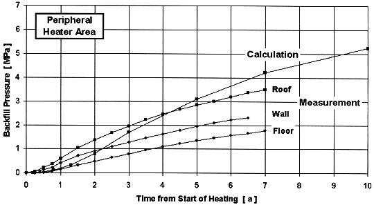
Fig. 5. Backfill pressure in the heated ar
eaIn view of the great impact of the backfill on repository safety performance, it is necessary to predict its behavior under conditions similar to those expected for a repository. In order to perform repository safety assessment, different computer codes and user models have been developed in the past. These codes and models must be verified, validated, and analyzed with regard to their predictive capability. Therefore, a benchmark exercise "Comparative Study on Crushed Salt" (CS2) is carried out under participation of six modeling groups. The main emphasis is to further refine the constitutive models developed in the past to describe the backfill behavior. The objective is to
Various constitutive models for crushed salt have been developed by the modeling groups. Because of the complex behavior of the crushed salt, the constitutive models contain a great variety of material parameters which have to be derived from laboratory tests. The benchmarking exercise provides a means of comparing and calibrating the constitutive models. The following table presents the participating modeling groups and their models.
Table I. Modeling groups, codes, and constitutive models in the benchmarking exercise
|
Modeling group |
Code |
Constitutive Model |
|
GRS (subcontractor DBE) |
MAUS-2/ -5 |
Hein (deviatoric) |
|
ECN |
ANSYS |
Spiers |
|
FZK/INE |
MAUS-5 |
Hein (deviatoric) |
|
G.3S |
GEOMEC |
Cam-Clay modified |
|
ENRESA (subcontractor CIMNE) |
CODE BRIGHT |
FADT + DC |
|
BGR |
ANSALT I |
Zhang/Heemann (deviatoric) |
The benchmark consists of three progressive stages:
The objective of this benchmarking is to provide modeling tools to predict the performance of crushed salt backfill under repository conditions and to create a basis for exchange and transfer of modeling expertise.
In 1999, after more than eight years of heating, the heat power will be continuously shut down over a six to twelve months period according to current planning. However, no definite timetable has been set yet. A post-heating investigation programme will be carried out from 1999 to 2001.
The experiment will improve the understanding of processes relevant to backfill and rock salt behavior in heated emplacement drifts. The numerical models that extrapolate forward these processes will be refined and calibrated.
BOREHOLE EMPLACEMENT: THE DEBORA TESTS
The DEBORA (Development of borehole seals for radioactive waste) experiments investigate the backfill behavior in the annulus between HLW canisters and borehole wall and in the seals of HLW emplacement boreholes. The objective is to determine the interactions between backfill and near-field rock salt and to develop further the numerical models to simulate these processes (Rothfuchs et al., 1996). According to the borehole emplacement concept, the canisters will be stacked in 300-m-deep boreholes. Backfill will be emplaced around the canisters to distribute the stacking load of the canisters to the surrounding rock. The boreholes will be sealed against the drift above by emplacing backfill material in the upper 30- to 40-m part of the borehole.
In the early phase, the backfill will have a rather high porosity and permeability providing a flowpath for brine and gases. However, as a consequence of rock convergence, the backfill will be compacted and the flowpath closed. Numerical models that are based on laboratory data have been developed in the past to describe the performance of backfilled emplacement boreholes. These models are refined and calibrated by comparing in situ data with calculational results.
The experiments are carried out in two separate boreholes (Fig. 6). DEBORA 1 is carried out in a 600-mm-diameter and 14-m-deep borehole beneath a drift 800 m deep in the mine. A liner in the borehole represents the waste canisters in a disposal borehole. Electric heaters inside the liner produce 9 kW of power. In a 15-months testing period, the heat induced compaction of the backfill between the liner and the borehole wall and the related decrease of porosity and permeability are investigated. The experiment is operational since February 1997.
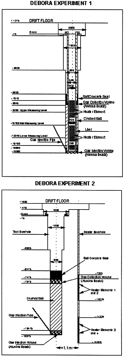
Fig. 6. Vertical sections of the DEBORA 1 and DEBORA 2 experiments
DEBORA 2 (Fig. 6) is also carried out in a 600-mm-diameter and about 14-m deep borehole located 15 m away from the DEBORA 1 borehole. In the lower 5.5 m of the borehole crushed salt is emplaced. This part, simulating the seal of an HLW disposal borehole, is heated by four external peripheral heaters producing 3.5 kW each (14 kW in total). Measurements are also focused on the interrelationship between backfill compaction, temperature, pressure, convergence, and permeability. The experiment became operational in September 1997.
Heating of the DEBORA 1 borehole led to a rapid increase of the backfill temperature to about 180 °C. The temperature is only slightly rising during the further course of the experiment. In the DEBORA 2 experiment the temperature increase is not that fast because the heaters are located outside the central borehole at a radial distance of 1.1 m. In both experiments the heat induced borehole convergence (closure) is being measured at three levels at depths of 10.5, 12, and 13.5 m below the drift floor. The decrease of backfill porosity is determined on the basis of borehole convergence measurements. For both experiments, Figure 7 shows the comparison of the measured and predicted development of the porosity 12 m below the drift. The predictions were made with the code Supermaus (Breidenich, 1993) under consideration of a constitutive equation describing the thermomechanical behavior of crushed salt published by Hein (1991). In both cases, the measured compaction rates are smaller than predicted; so a further improvement of the used models seems to be necessary.
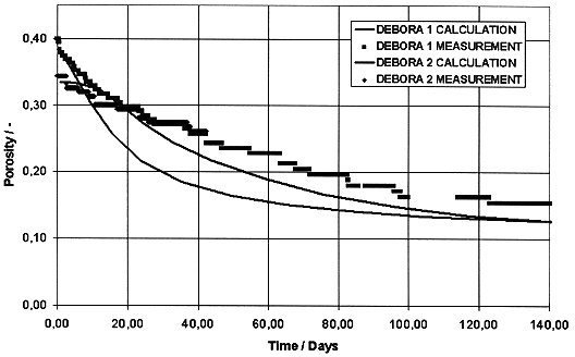
Fig. 7. Comparison of the measured and predicted development of the porosity 12 m below the drift
The decrease in permeability of the crushed salt is determined by periodical flow tests. During these tests, a stationary nitrogen gas flow is being set up between a gas injection volume and a gas collection volume. Measurement of the input and output gas pressure, of the nitrogen inflow and outflow rates, and of the gas temperature enable evaluation of Darcy's law for stationary gas flow. During the time period between February and September 1997, the permeability of the crushed salt in the DEBORA 1 experiment decreased from initially 4× 10-12 m2 to 1.5× 10⁻¹³ m2. In the DEBORA 2 experiment only one measurement could be performed so far indicating an initial permeability of approximately 3× 10⁻¹⁰ m2.
The DEBORA experiments are scheduled to be terminated by the end of 1998. It is planned to uncover the boreholes by a new access drift and to analyse the spatial distribution of porosity and permeability in the compacted backfill.
THE ALOHA PROJECT
The project ALOHA deals with the investigation of the excavation disturbed zone (EDZ) around cavities in salt formations. The objectives of the project include the characterization of the hydraulic behavior of the EDZ and the investigation of its extension. Its development with time, i.e., the reduction of the EDZ after placing a bulkhead and subsequent stress build-up, cannot be investigated directly. Instead, the relation between stress state and hydraulic properties of the salt has to be considered.
The investigation program consists of a series of in situ measurements backed by laboratory and modeling works. The in situ activities include
The in situ measurements are performed in a test drift at the 875-m-level of the Asse salt mine. A plan view of the test drift (cross section about 4.5 m by 4 m) and a schematic view of the test borehole arrangement are given in Figure 8. Two parallel vertical boreholes of 25 m depth and 56 mm diameter in the drift floor are used for the injection tests with gas and liquid, respectively. The liquid injection borehole is surrounded by another five boreholes containing the electrodes for the geoelectric measurements. Additionally, three electrode profiles are located on the drift floor.
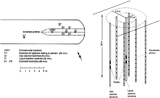
Fig. 8. Plan view of the test drift and schematic view of the test boreholes of the ALOHA project
The laboratory program concentrates on the investigation of material parameters relevant for two-phase flow (relative permeabilities and capillary pressure curves), since these are relevant for the system rock salt - brine - gas, but cannot be determined in situ. Hydraulic and mechanic modeling for layout and interpretation of the test results (especially comparisons between stress state and hydraulic behavior) complete the investigation program. This work, however, concentrates on the results of the in situ tests.
During 1997, a series of gas injection tests were conducted at borehole depths between 1 m and 20 m. For the tests a hydraulic multipacker system that can be moved in the borehole was used. It consists of four sealing elements of 0.5 m length each. They are separated by an upper and lower observation interval of 0.3 m length and an intermediate test interval with a length of 0.8 m. The sealing elements are inflated by oil up to a pressure of about 8 MPa. After the packers have settled (about one day after inflation) the test gas (nitrogen) is injected at a constant flow rate of 500 - 550 ml/min into the test interval. When the maximum pressure of 3 MPa (2 MPa for the measurement at 1 m depth) is reached, the test interval is shut in and the pressure decay is monitored. Flow rate and pressure data are recorded by a PC-based data acquisition system. From the measured data permeability is derived using the computer code WELTEST (Intera, 1992) which iteratively minimizes the root mean square deviation between measured and calculated pressure values.
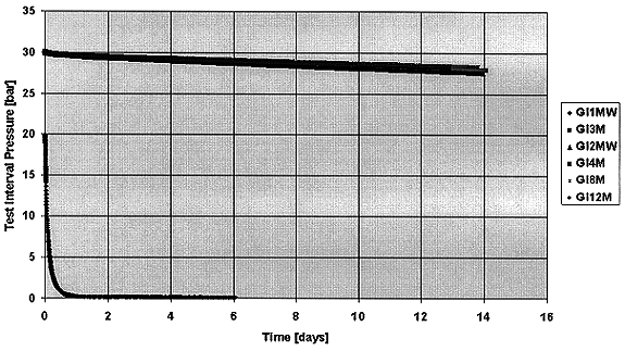
Fig. 9. Gas pressure development during the shut-in phases of the injection tests between 1 m and 12 m depth
The pressure decay during the shut-in phases of the injection tests between 1 m and 12 m depth is shown in Figure 9. It can be seen that all pressure curves except for the one referring to the measurement at 1 m depth are nearly identical. During the two weeks of measurement the pressure decreases only by about 0.2 MPa. Since this pressure decrease is already in the range of the system's untightness, only an estimate of the permeability can be made, giving a result below
10-21 m2. The test at 1 m borehole depth shows a completely different pressure curve. The evaluation yields a value of 2 × 10-17 m2. Thus, it can be stated that the extension of the EDZ is below 2 m, and that the permeability contrast is at least four orders of magnitude.
For the liquid injection tests a double packer system similar to the one for the gas injection tests was used. The brine was injected by a pump; the injected amount was measured both by a flowmeter and by continuous weighing of the brine container. An overview of the complete system is shown in Figure 10.
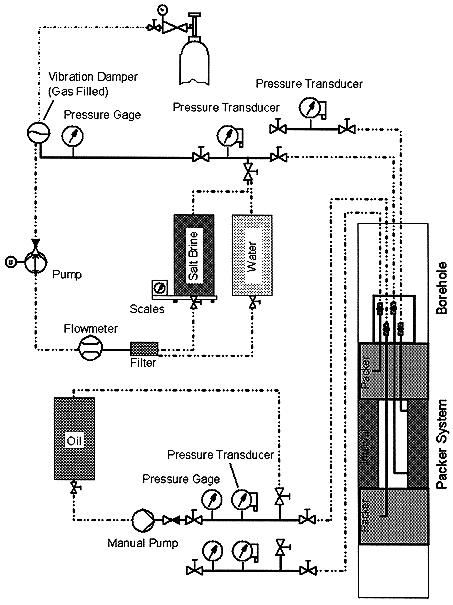
Fig. 10. Overview of the liquid injection system
Liquid injection tests were performed at depths of 1 m, 2 m, and 20 m. During the tests at 2 m and at 20 m depth it was impossible to inject a significant amount of liquid with a maximum injection pressure of 6 MPa, a result which is in agreement with the gas injection tests. During two liquid injection phases at 1 m depth a total amount of 7.5 litres of brine was injected. The second injection phase was evaluated with WELTEST and gave a permeability in the range of 10-14 m2. This high value (compared to the gas injection tests) leads to the assumption that the brine follows a flowpath (e.g., a fracture) instead of spreading uniformly into the pore space. This assumption is confirmed by the results of the geoelectric measurements.
The geoelectric measurements are performed by injecting a current by two electrodes into the rock and measuring the potential difference between two other electrodes. By varying the injection and measurement electrodes a distribution of the electric resistivity in the rock can be obtained. The resistivity of rock salt is connected to its moisture content by a well-established proportionality. Thus, the geoelectric measurements yield the moisture distribution in the rock.
In Figure 11a the resistivity distribution in the planes between the electrode boreholes surrounding the liquid injection borehole is shown. It can be seen that the resistivity at 2 m depth and below is in the range of 5000 - 20000 W m (corresponding to a moisture content of 0.06 - 0.1 Vol.-%). At the injection depth between 0.5 and 1.5 m a resistivity between 200 and 1000 W m is measured, which corresponds to a moisture content between 0.3 and 0.5 Vol.-%. It can, however, also be seen that the resistivity in the plane between the boreholes 51 and 53 is significantly lower than in the perpendicular plane. This effect is even clearer in Figure 11b where the extent of a "500-W m-cloud" as derived from the measurements is shown. From the results of these measurements it is concluded that there is a preferential pathway for the brine, possibly a fracture or a high-permeable sulfatic layer. An overcoring of the liquid injection borehole is planned to confirm the interpretation.
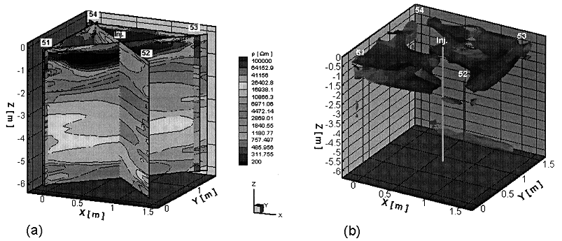
Fig.11. Distribution of the electric resistivity in the planes between the electrode boreholes after the liquid injection tests (a) and extent of a "500-
W m-cloud" (0.35 Vol.-% water content) (b)CONCLUSIONS
The sealing capacity of backfill and rock salt in a salt repository are investigated by different In-situ experiments in the Asse salt mine by simulating drift and borehole emplacement.
In the TSS test the backfill behavior in emplacement drifts is investigated. Measurement results are available over more than seven years. Temperatures predicted by thermal model calculations are confirmed by the measurements. The drift closure was accelerated considerably by heating. Drift closure rates and backfill compaction, however, are significantly slower than expected. The backfill pressure has reached only 24 % of the initial vertical stress estimation of 12 MPa in the test field. This value is significantly lower than the expected lithostatic pressure of 18 MPa due to the influence of former mining activities in the Asse salt mine. Additional calculations and improvements of the numerical models by benchmark calculations with different codes are planned to refine a prediction of the behavior of crushed salt backfill under repository conditions.
In the DEBORA project model calculations were performed to predict the heat induced compaction and porosity decrease in simulated HLW disposal boreholes in the Asse mine. Preliminary results of the experiments started in February 1997 and scheduled to be terminated by the end of 1998 indicate a slower compaction and thus a slower decrease of the porosity and permeability of the crushed salt than predicted in the calculations. The used models are to be improved by further laboratory investigations on crushed salt compaction behavior.
In the ALOHA project an excavation disturbed zone extending less than the drift radius into the salt rock was found. The EDZ provides a significant pathway to both gas and liquid with a permeability contrast of at least four orders of magnitude compared to the undisturbed rock.
REFERENCES
ACKNOWLEDGEMENTS
The works were funded by the Federal Ministry for Education, Science, Research, and Technology (BMBF). The TSS test and the DEBORA tests are co-sponsered by the European Commission.