DEVELOPMENT OF ADVANCED DECONTAMINATION TECHNIQUES
FOR DECOMMISSIONING
Yutaka KAMEO, Kazuhiro AOKI, Hiroshi OUCHI, Takeo GORAI, Takakuni
HIRABAYASHI
ABSTRACT
An attempt has been made to develop the decontamination techniques of gas carrying abrasive method and in-situ remote electropolishing for pipes before dismantling. The grinding parameters -i.e. abrasive material and its concentration, abrasive supply method and flow velocity- were optimized for the gas carrying abrasive method. Abrasive was supplied by the suction supply method, which gave high grinding power over wide area. Flow velocity had more significant effect than concentration of abrasive on grinding power. Cast iron grit had not only long lifetime but also suitable grinding power. The materials of internal cathode were selected to make in-situ remote electropolishing equipment. Tests of the equipment were carried out and following results were obtained. Electropolishing rate and current efficiency were 1.45m m/min and 75%, respectively, under the initial electrolyte temperature of 50? and anode current density of 0.1A/cm2. The traveling machine could sufficiently pull the 200A type electropolishing part and pass through bend pipes and also climb up vertical pipes.
INTRODUCTION
Decontamination of concrete, pipes, and components before and after dismantling is very important to minimize occupational dose of dismantling worker and reduce volume of radioactive waste. The Japan Atomic Energy Research Institute (JAERI) developed efficient decontamination techniques, such as Sulfuric acid - Cerium chemical method1-2) and wet flowing abrasive method 3), for decommissioning of the Japan Power Demonstration Reactor (JPDR). It is necessarily to reduce drastically the amount of secondary waste that will be generated in future decommissioning of commercial nuclear power plants. While there are various decontamination techniques such as chemical method, electrochemical method, abrasive blasting method, etc., the generation of a large amount of secondary waste becomes a serious problem. Therefore, JAERI have been developing advanced techniques for decontamination with a small amount of secondary waste since 1990.
These techniques are as follows:
Decontamination for pipes before dismantling
Decontamination for components after dismantling
The present paper discusses the details of the decontamination techniques for pipes.
A. GAS CARRYING ABRASIVE METHOD
Outline
The wet flowing abrasive method has been developed and given good results for decommissioning of the JPDR. It is, however, difficult to apply this method to the decontamination of commercial nuclear power plants, because it will need a large circulation pump and a large amount of contaminated liquid waste will be generated. Gas carrying abrasive method using swirling flow of air and abrasive, therefore, has been developed. This method is a dry method and possible to apply large pipes. The objects for this development are the optimization of grinding parameters -i.e. abrasive material and its concentration, flow velocity, and diameter of pipe- to obtain high decontamination factor and also the optimization of classification parameters for separation of abrasive and dust to reduce the volume of secondary waste. The present paper discusses only the optimization of grinding parameters.
The gas carrying abrasive equipment is composed of an abrasive supplier, a test section with removable specimens, a classification section for separation of abrasive and dust, and a collecting section for dust. The test section consists of 6m of horizontal pipe, 1m of bend pipe, and 3m of vertical pipe. Removable specimens can be mounted on nine parts; each part has four specimens at hoop direction.
Abrasive supply method
Two abrasive supply methods were examined -viz. (a) compulsion supply method, (b) suction supply method. The compulsion supply method is the way to project abrasive into pipe with pressurized air; the suction supply method is the way to suck abrasive under the negative pressure into the inside of pipe.
Tests were carried out for 200A pipe by compulsion supply method and suction supply method using 20wt% of alumina powder under the flow velocity at 30m/sec and grinding time of 5hours. Figure 1-(a) shows the comparison of grinding patterns of the compulsion supply method and the suction supply method. By the compulsion supply method, the pipe was deeply ground near the abrasive supply nozzle but slightly far from it. By the suction supply method, the pipe, especially horizontal part was uniformly ground. The similar tendency was observed in the case of another diameter of pipe and flow velocity.
The reduction of grinding depth in the bend part may be attributed to turbulence of the swirling flow and temporary drop of flow velocity. The suction supply method is more effective than the compulsion supply method, since the former gives higher grinding power over wide area than the latter. After this examination, tests were carried out for 100A pipe by suction supply method using alumina powder under the condition of flow velocity at 30m/sec, abrasive concentration of 20wt%, and grinding time of 2 hours, unless otherwise noted.
Grinding patterns of 100A and 200A pipe
Figure 1-(b) shows the comparison of the grinding patterns for 100A and 200A pipes at flow velocity of 50m/sec.
In the case of 100A pipe, the grinding depth increased slightly with distance from the abrasive supply nozzle because of the higher flow velocity with approach to the blower. In the case of 200A pipe, the grinding depth decreased with distance from the abrasive supply nozzle. This is because the swirling flow is formed easier in 200A than 100A pipe and weakens with distance from the abrasive supply nozzle.

Fig. 1. Comparison of Grinding Patterns.
(a) Compulsion and Suction. (b) 100A and 200A
Grinding Power And Consumption Rate Of Abrasive
Figure 2-(a) shows the comparison of the abrasive materials and the grinding depth. The grinding power of alumina powder is very high and the order of grinding power of abrasives is as follows:
alumina powder > cast iron grit >> stainless steel (SUS) cut wire
High grinding power of alumina powder was attributable to its hardness and sharp edge.
Figure 2-(b) shows comparison of the consumption rate and the grinding time. Cast iron grit and SUS cut wire were little consumed and the order of the consumption rate is as follows:
SUS cut wire < cast iron grit << alumina powder
The consumption rate of alumina powder is relatively high, so that the generation of secondary waste would increase. The consumption rate of cast iron grit is quarter of alumina powder, while the grinding power of cast iron is less than alumina powder. Therefore, cast iron grit is more suitable for reducing secondary waste.

Fig. 2. Comparison of Abrasives.
(a) Grinding Depth vs. Grinding Time. (b) Consumption Rate vs. Grinding Time
Effect Of Concentration Of Abrasive And Flow Velocity
Figure 3-(a) shows the relation between concentration of abrasive and grinding depth. The grinding depth increased with concentration of abrasives, especially cast iron grit. This is because specific gravity of cast iron grit is higher than that of alumina powder.
Figure 3-(b) shows the relation between flow velocity and grinding depth for various abrasive materials. The difference of grinding depth for each abrasive especially the superiority of alumina powder become more obvious in higher flow velocity, although it is not clear in low flow velocity. Doubling the flow velocity increased grinding depth by a factor of 15 for alumina powder, and by a factor of 4 for SUS cut wire. This fact showed flow velocity to be very important factor for the grinding power.

Fig. 3. Relation Between Grinding Depth and Grinding Parameters.
(a) Concentration of abrasive (b)Flow Velocity
CONCLUSION
The grinding parameters -i.e. abrasive material and its concentration, abrasive supply method and flow velocity- were optimized for the gas carrying abrasive method. The results are as follows:
B. IN-SITU REMOTE ELECTROPOLISHING
Outline
In-situ remote electropolishing technique for decontamination of pipes before dismantling is expected to reduce occupational dose of dismantling worker and secondary waste, since electropolishing technique has been examined and demonstrated to be effective for decontamination after dismantling. In-situ remote electropolishing decontamination is superior to chemical decontamination that is generally applied for system decontamination, since the former will be applicable to partial decontamination of pipes and not in need of complicated processing for liquid waste and generate less amount of secondary waste than the latter.
The equipment for in-situ remote electropolishing technique needs,
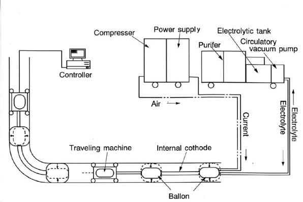
The equipment is composed of an internal cathode, a pair of balloons for making a closed inside area of pipes for decontamination, a machine traveling along inside of pipes, an electrolyte circulatory vacuum pump, and a DC power supply.
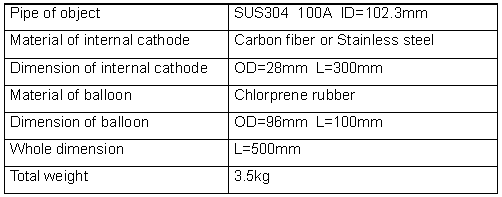
Figure 4 shows the assembled equipment. The specifications of internal cathode are shown in Table I.

Fig. 4. Electropolishing Decontamination System
Table I. Specification of Internal Cathode of Traveling Type

The electropolishing decontamination will be carried out as follows:
Materials Of Balloons And Internal Cathode
Immersing tests in 80% of phosphoric acid at 60? were carried out for chloroprene rubber and chloro-sulfonation polyethylene rubber to examine their properties, such as tensile strength, elongation percentage, break strength, wear and corrosion resistance, and dimensional stability.
Chloro-sulfonation polyethylene rubber changed little even after aging, and it was proved to be more suitable than chloroprene rubber. It was, however, relatively difficult to make the balloon of chloro-sulfonation polyethylene rubber. For this reason, the balloons were made of chloroprene rubber for this once.
Electropolishing tests were carried out by using internal cathode made up of carbon fiber bundle or flexible stainless steel tube to obtain the data on temperature rise of electrolyte.
Bundling a number of carbon fiber led to increasing surface area of internal cathode and decreasing current density of it. Carbon fiber bundle produced little heat, and electrolyte was kept low temperature. As a result, the lifetime of electrolyte was improved and the generation of mist of electrolyte was suppressed.
On the other hand, surface area of flexible stainless steel tube is smaller than that of the carbon fiber bundle, but flexible stainless steel tube kept low temperature of electrolyte. This is because electrical resistance is low for stainless steel. From the standpoint of temperature control of electrolyte, flexible stainless steel tube was superior to carbon fiber bundle.
Confirmation Of The Performance
Electropolishing tests were carried out for 1 hour using horizontal pipe and stainless steel internal cathode. The results obtained are shown Table II.
Table II. Electropolishing Rate and Current Efficiency

Current efficiency of electropolishing is generally higher at higher temperature, while the gas evolved at 0.2A/cm2 and stayed in the upper inside of pipe may cause the decrease of current efficiency.
Vertical pipes were also electropolished. The tendency of electropolishing was similar to horizontal pipe, but the electropolished surface was more uniformly than the horizontal pipe, because of short stay of evolved gas.
Traveling Machine
A traveling machine was made for pulling the 200A type electropolishing part. Performance tests were carried out using the equipment combined traveling machine and electropolishing part. The equipment could sufficiently pass through bend pipes and also climb vertical pipes.
CONCLUSION
The materials of internal cathode were selected to make the in-situ remote electropolishing equipment. Tests of the equipment were carried out and the results are as follows:
ACKNOWLEDGMENT
This work was performed under contract with the Science and Technology Agency of Japan, for which authors express their appreciation.
REFERENCES
T. Suwa et. al., "Chemical Decontamination Process with Sulfuric Acid-Cerium(IV) for Decommissioning, - Decontamination of Dismantled Components -", JAIF Int. Conf. on Water Chem. in Nuclear Power Plants, pp737- 742, Hukui City, Japan. (1988 )
T. Suwa et. al., "Chemical Decontamination Process with Sulfuric Acid-Cerium(IV) for Decommissioning, System Decontamination Process with Electrolytic Regeneration of Ce4+ from Ce3+", J. Nucl. Sci. Technol., 25, 574 (1988).
T. Momma et. al., "Flowing abrasive method for system decontamination in the Japan Power Demonstration Reactor", The 3rd JSME/ASME Int. Conf on Nuclear Engineering, pp1817- 1822, Kyoto, Japan. (1995)