
FOAMS FOR NUCLEAR DECONTAMINATION PURPOSES:
ACHIEVEMENTS AND PROSPECTS
M. Faury, B. Fournel, G. Boissonnet, H. Provens
Commissariat à l'Energie Atomique
CE Cadarache, 13108 St Paul Lez Durance Cedex
faury@desdcad.cea.fr
ABSTRACT
During the decommissioning of a nuclear facility, most of the material requires disposal and may therefore warrant decontamination. Only a few techniques are available to decontaminate large internally contaminated components with complex shapes. Among these techniques, the foam process seems to be the most efficient for it only requires small amounts of liquid. Thus, the volume of secondary waste produced can be significantly reduced. This process was successfully validated during the decontamination of a graphite-gas cooler representing a developed area of 1000m2. Since then, there has been an increasing number of studies on new foam formulations adapted to maintenance or dismantling purposes. For a better mastery of this process, comprehensive studies are ongoing. They consist of the characterization of decontamination foams, using image analysis and an approach of the rheological behavior of such a fluid.
INTRODUCTION
Decontamination is an important procedure because it not only reduces radiation during decommissioning operations, but also has the potential, for decategorization of waste, to achieve lower disposal costs.
Only few techniques are available to decontaminate large internally contaminated components with complex shapes such as valves, reservoirs, heat exchangers, turbines, vessels, boilers. Mechanical methods are inoperative for it is impossible to reach all the internal surfaces. Moreover, the retrieval of the abrasion residue is difficult. Immersion systems are not feasible. First, because the volume of reactants would be too great, second, because reactants are ineffective on large volumes due to boundary layer phenomena. The foam application process provides good solutions to all these problems. This process is based on the filling of the equipment with liquid foam containing suitable chemical reagents, and its recirculation through a recycling loop. The major advantage of this technique is the use of only small amounts of liquid. Thus, the volume of secondary waste produced can be significantly reduced ( about 10 times less than with conventional decontamination methods such as recirculation of liquid). Moreover, foams are able to forcefully penetrate everywhere, reaching the interstitial gaps, acting on all contaminated surfaces. Furthermore, the effectiveness of the process is enhanced by the dynamic motion of the foam and its permanent regeneration on the component walls. Common problems resulting from boundary layers should thus be minimized. And finally, the recirculation of the foam and the continuous filtration of the stock solution allow the treatment to be pursued until decontamination is fully achieved.
ACHIEVEMENTS
Industrial Application of the Foam Process
The foam process was successfully validated on an industrial scale during the decontamination of a graphite gas-cooler in 1993. This work was conducted within the context of an EU program [1].
The characteristics of the gas-cooler were the following :
The decontamination device presented in Figure 1 consisted of two tanks (C01 and C02) and three units : one foam generation unit and two filtering units. The process was based on the filling of the equipment with liquid foams containing suitable reagents.
The foam process was applied in the three steps described in Table I : degreasing, descaling and rinsing. The foam formulation was taken from a CEA patent [2]. The advantage of this formulation is that it can be used either in an acid or alkaline environment (up to 5 mol/l). During this industrial demonstration, proof was made of the feasibility and the effectiveness of the foam process. The circulation of the foam was mastered, the quality of the foam was excellent and grease particles and large copper chips (about 10 cm2) were thus removed. Moreover, the decontamination operation only produced 6m3 of effluents i.e. 6.2 l/m2 of treated components. Decontaminating an identical cooler using a chemical solution would have produced approximately 10 times more effluents for a similar result. A decontamination factor (ratio between the initial and final activity) of up to 190 was obtained, leading to a residual activity of below 1 Bq/cm2.
Table 1. Foam Process & Operating Conditions

Similar results were obtained during the decontamination of large valves (40m2) [3], or heat exchangers (232 m2) [4].
All these examples established that, for geometrically complex equipment, it was possible to limit secondary waste while maintaining (and even improving) adequate efficiency standards. Since these achievements, increasing studies have been undertaken to develop new foam formulations adapted to maintenance or dismantling purposes. At the same time, comprehensive studies were also necessary for a better mastery of the process. These studies rely on the characterization of decontamination foams through the use of image analysis and on a better understanding of the rheological behavior of such a fluid. The final aim of this work is to predict the flow properties of foams in facilities with different geometries.

Figure 1. Foam decontamination device - industrial demonstration.
COMPREHENSIVE STUDIES ON DECONTAMINATION FOAMS
Structure and Stability of Decontamination Foams
The aim of this study is to characterize the liquid film in contact with the wall since this is where decontamination occurs. Bubble size distribution and interfacial areas are of great interest since film characteristics are linked to foam structure. Drainage is also studied because it directly influences film thickness. In these experiments, flowrates are low (3.9x10⁻⁵ to 9x10⁻⁵ m3s-1 at atmospheric pressure) and residence times are high ( 10 to 20 min.) in order to favor drainage. Numerical images of a foam flowing vertically in a column (1 meter high) are taken and then processed to measure such geometrical properties as bubble size distribution, mean equivalent diameter and 2D expansion ratio, which corresponds to the ratio between the total area and the liquid film area.
Photographic devices have been used since the mid 80's. Kroezen et al.[5] used a photographic device in order to measure bubble size distribution in a rotational rheometer. Calvert et al. [6] and Gido et al. [7] used it to study the structure of a flowing foam. This type of device has the major advantage of preventing interaction with foam and does not influence foam structure. Recent progress in electronics and especially in CCD sensors and numerization cards allows a CCD camera coupled with an appropriate computer to deliver 25 numerized images per second with a high resolution.
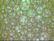
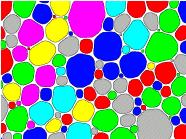
In our experiments, the CCD camera gives colored images (presented in 256 gray levels, in Figure 2a). The role of the image treatment is to isolate the significant information contained in an image, such as bubble outline, by increasing image contrast thanks to linear and non-linear filters. After thresholding, a binary image which contains too much noise to be analyzed (Figure 2b) is obtained. Image cleaning and bubble filling are necessary, after which (Figure 2c) measurements are possible.
 a
a b
b
 c
c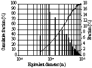 d
d
Figure 2.(a) Original image (b) Processed and thresholded image (c) Labelled image ready for measurements (d) Bubble size distribution
The bubble size distribution represented in Figure 2d is based on 10 images corresponding to almost 700 bubbles which do not touch image edges. Several distributions have been built for different operating conditions. Distribution shapes are identical whatever the operating conditions.
In a first approximation, bubble size distribution seems to be log-normal, which is in agreement with other studies using other measurement methods or under other operating conditions [6,8]. This curve could also be fitted by an exponential distribution such as :
R = A r exp (-Br2) |
(1) |
where R is the cumulative fraction of bubbles with a radius smaller than r. Some bibliographical research is in progress to find an answer to the question of bubble size distribution shape.
Studying the bubble mean diameter, we observed that it does not vary much with decontamination operating conditions. Then the following assumption was made : wall effects could be more powerful on the foam external structure than bulk effects, such as foam generation or flowrates.
By comparing 3D expansion ratios measured by sampling and 2D expansion ratios measured at the wall by image analysis, the hypothesis of the wall effect was confirmed. In particular, wettability and liquid film influence the structure at the wall. Studying expansion ratios as a function of foam flowrate at different heights in the column, it was noted that F3D is always greater than F2D and that F3D increases by a maximum factor of 5 instead of a maximum factor of 2 for F2D. As for foam structure, the resulting hypothesis is that the wall phenomena seem to be more important than the bulk ones on F2D.
Wall effects seem to influence local expansion ratios and bubble size distributions, more than bulk effects. Considering that F2D variations with height are lower than those of F3D, the liquid film could be relatively uniform along the column. This is a positive factor in the context of a decontamination operation.
Decontamination Foam Rheology
The experimental device is composed of a 32 m long pipe with an inner diameter of 30 mm. Foam velocity ranges from 0.1 to 0.8 m.s-1 and residence time is low (30 sec. to 5 min.). Thus, drainage is limited, whereas it was favored in the previous study. Ql, Qg0, Qm0, and F0 are defined as follows :

F is the expansion ratio using Qg, the gas flowrate, which is corrected with the pressure value, assuming that the gas is ideal.
Preliminary studies related to the pressure drop along a pipe showed that the volumic gas fraction plays a role in rheological behavior and that compressibility cannot be neglected. Considering that foam is a dispersed medium, a specific flow model must be defined. A model defined by Valko et al. [9,10] seems to be well adapted to the study of foam rheology because it combines a conventional model with the foam compressible property, using the Volume Equalizing Principle. This consists in studying the rheology of a fluid with corrected variables which take into account the compressibility of the fluid.
Figure 3 shows a flow diagram using the equalized shear rate ![]() and the equalized shear stress t
p* where t p* = t
p/e and ,
and the equalized shear stress t
p* where t p* = t
p/e and , ![]() =
=![]() /e, e being the specific
expansion ratio defined by e = r l/r . It has been
built with experiments made on foams with expansion ratio F0 values of 10, 14
and 18. A bijective relationship can be established between the two variables and the
diagram shows that an Ostwald de Waele model can be fitted. There is a drift only for high
flowrates and experimental points corresponding to the pipe inlet.
/e, e being the specific
expansion ratio defined by e = r l/r . It has been
built with experiments made on foams with expansion ratio F0 values of 10, 14
and 18. A bijective relationship can be established between the two variables and the
diagram shows that an Ostwald de Waele model can be fitted. There is a drift only for high
flowrates and experimental points corresponding to the pipe inlet.
Under these conditions, the actual expansion ratio F, is of about 5 or 6. Ne
r this limit, Calvert et al. [6] noted that foam structure changes, which could induce a modified rheological behavior.
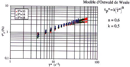
Figure 3. Flow diagram.
The values of the Ostwald de Waele model parameters do not depend on the F0 expansion ratio. They have been calculated by linear regression of curves plotted in Figure 3. Thus, the rheological equation is :
| |
(2) |
Knowing the rheological characteristics, a numerical method is used to calculate the pressure drop in a pipe.
A rheological model of a flowing foam taking compressibility into account has been found in the F0 and Qm0 domain studied. In future studies, the effect of a slip layer and the influence of pipe material will be thoroughly investigated.
By gathering the results of both comprehensive studies, we intend to be able to predict the hydrodynamic behavior in equipment of different geometry. Understanding the hydrodynamics will also allow us to improve our knowledge on mass exchanges during decontamination. This knowledge will also be valuable in support to all the emerging studies on foams for decontamination purposes.
PROSPECTS
The foam decontamination process has a great potential and the future prospects of such a technique are real. New foam formulations are being developed either for maintenance or dismantling purposes. Among the applications presently developed at the CEA, one can quote the following studies :
Foams Adapted to Dismantling Purposes
The formulation of foams loaded with strong oxidizing reagents such as Ce (IV) is an important milestone. The enhanced decontamination properties of nitric acid with Ce(IV) additive on stainless steel and inconel alloys are well known in liquid mediums.
The use of this mixture is especially relevant when an erosion of the material is needed to remove the contamination fixed in the oxide layer or in the metal itself. The idea is to adapt the liquid formulation to a foam formulation. Nevertheless, the difficulty of this study resides in finding suitable surface agents, which will not be degraded by the oxidizing reagent and will allow the formulation of foams with suitable properties (moisture, drainage etc...). For instance, the surfactants used for the decontamination of the gas-cooler (a mixture of betaine and glucoside) are not well adapted to Ce(IV) loaded foams. In less than two hours, all the Ce (IV ) is transformed into Ce (III) by reaction with the surfactants. Thus, this competitive reaction strongly reduces the effectiveness of the foam and the erosion yield of the material to be decontaminated. To solve this problem, a large number of surfactants have been tested and new formulations are being found through the use of specific surfactants. For example, amino oxide and fluorosurfactants allow the formulation of suitable foams for decontamination purposes within a scale of 24 hours
Secondary Steam Generator Cleaning
Steam generator secondary-side corrosion is an ongoing problem in PWR nuclear power plants. This corrosion is caused by contaminants, both particulate and dissolved species, which accumulate and concentrate in the steam generator. Corrosion products formed in the steam, feed, and condense system can result in hundreds of pounds of sludge deposits per year on steam generator heat transfer and support structure surfaces. The accumulation of corrosion products and aggressive species has been linked to tube corrosion damage, water level control problems, and decreased power output. Fortunately, such deposits can be removed through chemical cleaning. Nevertheless, these cleaning methods produce a large volume of effluents. It was estimated that to remove the sludge, essentially composed of magnetite, 350 m3 were needed to clean one 1300 MW 6819 steam generator. If such a chemical solution could be adapted to a foam formulation, only 35m3 would be produced.
The aim of such a study is thus to formulate a foam capable of cleaning away the magnetite. While the volume of effluents is reduced by a factor 10, it is not possible to multiply the concentration of reactants by the same factor, in order to obtain the same efficiency in the total dissolution capability of the magnetite. Another foam property is used to counterbalance this dissolution capability which is the exfoliation property. If well formulated, foams are able to carry away solid particles. This property is also known as flotation and relies on interactions between particles and surfactants. Figure 4 shows for example, the effect of the choice in surfactants in enhancing flotation properties. The addition of SF cationic surfactant favors the transport of magnetite.
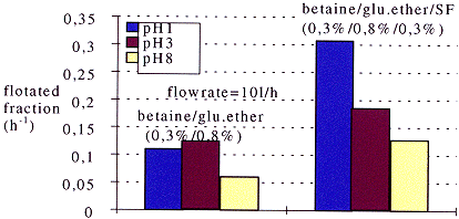
Fig.4 Flotation of magnetite versus pH and surfactant formulation
Decontamination of Depressurized Pipes
The use of foams is also relevant for the decontamination of depressurized pipes. For example, a foam formulation has been adapted to the maintenance of pipes in aluminum dedicated to the transfer of liquid samples from one building to another.. The formulation based on a phophonitric mixture allows the reduction of the activity to a level below 1Bq/cm2, by eliminating only 1.3 m m per hour. The formulation was also studied in terms of harmlessness. For instance, the rugosity of the material is maintained at a level of below 0.1mm. For such a task, foam generation technology was totally modified so that foam be transported through depression. The risk of radioactivity dissemination is thus minimized. At the same time, operating conditions were determined, so that the foam have a velocity high enough not to be degraded and to avoid a gradient in erosion and in decontamination effectiveness along the pipe.
CONCLUSIONS
The aim of this paper was to show how foam can be used in nuclear decontamination. The foam decontamination process has been industrially validated and two types of comprehensive studies are in progress in order to master it. The first one is the study of its structure and stability using image analysis under operating conditions which favor drainage. The second one is the study of foam rheology under operating conditions which limit drainage. Gathering the results of both studies, we intend to be able to predict the hydrodynamic behavior of foam in equipment with different geometries. Understanding the hydrodynamics will also allow us to further our knowledge on mass exchanges during a decontamination process. Such information will also be valuable in support of all the emerging foam formulations adapted either to maintenance or dismantling purposes. To conclude, the foam decontamination process should have a promising future.
REFERENCES