DECOMMISSIONING PROJECTS IN KRB A AND VAK
N. Eickelpasch
VAK, Kahl, Germany
H. Steiner, U. Priesmeyer
KGB mbH, Gundremmingen, Germany
J. M. Raymont
NUKEM Nuclear Technologies, Columbia, South Carolina
ABSTRACT
The decommissioning of the first generation of nuclear reactors in Germany is underway since 1983 in the Gundremmingen Unit A plant (KRB A) and since 1988 in the pilot nuclear power plant in Kahl (VAK). Although they are both of the boiling water type, they are rather different to each other with reference to their size and construction. As the first German nuclear power plant at all, VAK had to serve mainly scientific purposes. KRB A was the first commercial reactor in Germany.
The actual work is the dismantling of high contaminated components inside the reactor buildings and the underwater cutting of activated internals of the RPV`s. The decommissioning of KRB A is foreseen to be finished before the year 2000, the work in VAK will end about 3 years later.
The experience made in both projects are not limited on dismantling work only, but also include know-how on costs, effective decontamination techniques and scrap recycling.
INTRODUCTION
The two power stations, KRB A and VAK, represent the first generation of Boiling Water Reactors in Germany. VAK (Versuchsatomkraftwerk Kahl), located in Kahl, was Germany's very first nuclear power plant and served mainly scientific purposes, while KRB A (Kernkraftwerk RWE-Bayernwerk, Block A), located in Gundremmingen, was Germany's first commercial reactor.
The 250 MWe KRB A was in operation from 1966 to 1977 and the 16 MWe VAK's operational life ended in 1985 after 25 years. The decision to decommission KRB A was made in 1980 and work started in 1983. The dismantling of VAK began in 1988. The decommissioning objectives of the two units are quite different. Since KRB A shares its site with two 1300 MWe operating units, the buildings of KRB A will be kept as hot workshops. This contrasts with goal for VAK which is to directly proceed to a "green field" condition.
The decommissioning work on these two plants entails the disassembling of highly contaminated components inside the reactor buildings and the underwater cutting of the activated internals of the reactor pressure vessels. The experience gained from both projects is not limited to dismantling work alone, but also includes know-how on effective decontamination and scrap recycling procedures /1/.
While both VAK and KRB A are early boiling water reactor designs, there are differences in size and construction. A General Electric design, KRB A had three secondary circuits with recirculation pumps and steam generators to feed the turbine with supplemental steam. In the case of VAK, an AEG design, the steam generator separated the secondary circuits, so that the turbine hall was not part of the controlled area.
The dismantling experience gained at KRB and VAK can be applied to the decommissioning of both boiling water and pressurized water reactors /2, 3/. A variety of tools were developed, tested, and utilized on the projects. The differences in plant design and resulting tooling requirements provides significant decommissioning experience allowing a comparison of the results from both projects /4,5/.
DISMANTLING KRB A . . .
Phase I of the dismantling work began in 1983 with the removal of the components and systems in the turbine house. About 4,500 tons of low-level contaminated material and up to 100 Bq/cm2 were removed from the turbine hall. The total collective dose was not more than 1 Sv.
Phase II began in 1990 and continues today. At this point in the project about 700 tons of material representing the highly contaminated primary water system and equipment were removed from within the reactor building. These were mainly the recirculation systems with the pumps and steam generators, and the cleanup and shutdown cooling systems. The contamination levels were up to 50,000 Bq/cm. Now that most of the work is done, the original radiation dose estimate of about 1.4 Sv appears to be correct.
In 1992, KRB A obtained the licence for dismantling the activated components, namely the reactor pressure vessel with its internals and the biological shield. This is Phase III of the decommissioning project and the work is under way in parallel to Phase II.
The estimated dose for Phase III is about 1.5 Sv and similar to the dose associated with Phases I and II. Achieving this low of a collective dose for Phase III is only possible through the use of underwater cutting techniques and remote controlled operations.
. . . AND VAK
The turbine hall has been dismantled completely. Although this section was not part of the controlled area, numerous measurements had to be done to prove that there was no contamination. Today the main work effort is the removal of the reactor pressure vessel internals. A feature unique to VAK, and similar to pressurized water reactors, is that the spent fuel pool is located outside the reactor building. This is why the reactor internals have to be segmented and packaged within the reactor pressure vessel. As a result, the job calls for tools that are small and easy to handle.
The VAK project is carried out in close co-operation with KRB A. As an example, VAK's turbine hall is used to test and qualify the tools for dismantling work at both VAK and KRB A. For this purpose a test basin was built in which procedures and equipment are tested and demonstrated on a full scale mock up.
DISMANTLING TECHNIQUES
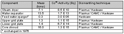
Figure 1 shows the KRB A and VAK reactor pressure vessels and their internals. These components have to be segmented for easy handling. Due to the high dose levels, various underwater cutting and post-dismantling techniques where required to accomplish the segmentation. With VAK mainly mechanical techniques were applied but with KRB A both mechanical and thermal cutting techniques are used depending on the special cutting tasks as well as to gain experience and compare different strategies.
Table I. Dismantling of activated components in KRB A Gundremmingen
The working area in KRB A is larger than in VAK which allows disassembly to be carried out within the reactor pressure vessel as well as in the spent fuel pool and the storage pool for the steam dryer. Table 1 presents the vital statistics of the main components from KRB A's reactor vessel.
The plasma arc technique is the method-of-choice for underwater cutting. A plasma torch with 100 kW output power is installed in a special tool carrier which is mounted on a turntable in the steam dryer pool. The plasma torch can cut material up to 100 mm thick. The plasma torch is backed up by a mechanical hacksaw which is used for thin walled pipes and a hydraulic shear. The Contact Arc Metal Cutting (CAMC) technique is used to cut off small parts or material that could disturb the linear movement of a standard tool.
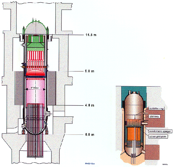
Fig. 1. KRB A Reactor (left) and VAK reactor
The first use for these tools was when the steam dryer was being dismantled (Figure 2). Thanks to an additional suction device and aerosol filtration the staff experienced no radiological problems. During cutting, visibility did not deteriorate nor did the specific activity of the water increase substantially. After decontamination, the low activated parts of the component were either released for nuclear recycling by melting or shipped to direct disposal.
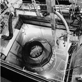
Fig. 2. Steam dryer during dismantling
Like the steam dryer before, the water separator was positioned on the turntable for dismantling. As the separator pipes are located very close to each other, a remote controlled cutting device, named Ramses, was developed which is able to clamp itself to the separator pipe and drive a small plasma torch around it by more than 360E. The maximum amperage of the plasma torch is 100 A, which allows it to cut a pipe with a diameter of 168 mm and a wall thickness of 7 mm in about one minute. Figure 6 shows the CAMC-tool connecting a graphite electrode in short circuit with the water separator to cut of a small part at a cyclone.
Another typical decommissioning task is the segmenting of highly contaminated heat exchangers or steam generators of different sizes. To deal with these large components, KRB developed and patented a new procedure called 'ice-sawing'. The basic idea is to fill a heat exchanger with water and freeze the total component for subsequent segmenting with a special band saw (Figure 3).
The ice-sawing technique was demonstrated on three steam generators in-situ. These were 8.8 m in height and 2.2 m in diameter. A large band saw was installed at the component using a vertical guide, which cut the generators into slices 0.8 m high. Ten cuts were made on each steam generator. It took about 8 hours to saw one segment.
The ice-sawing technique has the following advantages:
After post-segmenting, the ferritic steel parts were decontaminated from the high dose rate of about 20 mSv/h in maximum for free release. Only the austenitic tube bundles went to final storage; these were packed into drums after high pressure compaction.
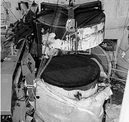
Fig. 3. Cutting And Lifting A Segment Of A Secondary Steam Generator With Ice-Sawing
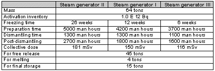
Table II shows the key information gained from dismantling the three steam generators and points out the reduction of time and collective dose of the work from the first to the third steam generator.
Table II. Dismantling Data For Three Steam Generators
In VAK an additional basin was adapted on top of the reactor pressure vessel to reduce area dose levels by raising the covering water depth (Fig. 4).
Conventional mechanical cutting techniques were used in special applications to dismantle the different internals. The sprinkler ring was cut into 24 pieces using a hacksaw. This took about 100 man hours. One third of this time was spent in preparation. The dose uptake was less than 600 FSv. The main advantages of the hacksaw are its high flexibility, the tool stiffness, and the generation of large swarf particles which minimizes underwater visibility problems.
The chimney above the core was cut using a nibbler. The nibbler was guided by the same tool support as used for the hacksaw. The hacksaw was used on the flange area of the chimney which is 25 mm thick. The nibbler required modification for underwater handling and to cope with the shape of the chimney, but it turned out to be a reliable tool with a high cutting speed. After 50 cuts through a material with a specific activity of 1.2 E08 Bq/g, the surface dose of the tool head went up to 100 FSv/h, which was lower than expected. The lower grid plate and the poison spray ring were also cut with the hacksaw.
The upper grid plate was cut using a grinder. This tool was supported by a special housing, in the shape of a fuel element channel. Every earlier position of a fuel element could be used as a cutting position, which made the handling very easy. The diameter of the grinder disc allowed it to do two cuts simultaneously. Tool change was done after every eight cuts and took only a short time. The surface dose of the disc did not exceed 50 FSv/h, which again was lower than expected.
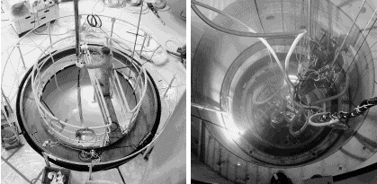
Fig. 4. Access To The RPV In VAK (Left) And Electro Discharge Machining, EDM
A more demanding cutting task was the dismantling of the condensate sparger ring. Because of its size and its position right next to the reactor vessel, conventional cutting tools could not be used. Different cutting techniques were tested using cold tests and finally electro discharge machining, EDM, was chosen to cut the ring into several angle sections (Fig 4.).
A special tool carrier was developed so that the core shroud could be cut vertically and horizontally with a milling machine. The upper part of the core shroud was successfully dismantled in the meantime. A high pressure water-jet cutting technique using suspended abrasives (WASS) was developed and qualified for segmenting the lower part of the core shroud. The patented WASS technique solved the generation of large amounts of secondary waste inherent with typical water-jet cutting and was selected for this first use in the field of nuclear dismantling.
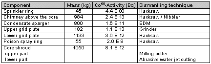
Table III summarizes the data on mass and activity of the internal components of the VAK reactor and gives the different cutting tools used for the specific dismantling tasks.
Table III. Dismantling activated components in VAK Kahl
DECONTAMINATION AND RECYCLING OF MATERIAL
The costs of a decommissioning project are mainly influenced by the dismantling approach with special consideration for waste minimisation. This fact became more important than ever, since in the German atomic law, recycling is no longer the preferred approach over direct disposal which became a viable alternative when the final storage site "ERAM" became available after unification occurred. As a result, cost now drives the decision of recycling vs. disposal /6/.
Still, one efficient way of reducing the radwaste is the decontamination of components for free release. For components with a defined shape and structure, which allow a measurement of the surface, this is usually done by removing the surface with mechanical or chemical procedures. If steel parts are to be re-used, German regulations specify the following activity limits:
Steel parts with residual specific activities between 0.1 Bq/g and 200 Bq/g qualify for 'nuclear recycling' by melting. Products with specific activities of less than 1.0 Bq/g can be manufactured for restricted re-used within the nuclear industry, i.e. as shielding containers.
In order to maximize recycling, an effective decontamination procedure for disassembled steel parts was called for. KRB A opted for electrochemical decontamination using phosphoric acid. This "electro-polishing" technique has been used in wide applications since the beginning of decommissioning work with great success at KRB A allowing the free release of most of the material from the three steam generators.
It is possible to recycle the phosphoric acid by adding oxalic acid to precipitate the dissolved iron as iron oxalate. This procedure was developed and patented at KRB A. The iron oxalate can be treated in a thermolysis to obtain iron oxide as an acceptable product for final storage. More than 1,000 tons of material was treated with this effective and most reliable procedure, which has reached decontamination factors of up to 100,000 for high contaminated components from the primary system.
After decontamination, only 1.5 % of the original mass of the steel components from the turbine hall was left as radioactive secondary waste in ferrous oxide form.
MEASURING TECHNIQUES
To release material for free re-use, it is necessary to have a powerful measuring technique, which allow to check the material in a short time and with reliable results. At the same time the output data should be evaluated in a way that the processing of the required documentation is simplified.
For the unrestricted release of material it is necessary to check 100 % of the surface. Plates and tubes for example can be measured in KRB A with special 200 cm-detectors, giving the required values of < 0.5 Bq/cm2 within a range of 5 seconds.
Another kind of measuring technique is required for material with undefined structures, like insulation material, broken concrete, or others. For this purpose a measuring device for drums is developed and used in KRB A, giving the specific activity as well as a profile of the dose rate.
By using this measuring device about 100 tons of broken concrete, were measured for free release at the end of 1996. In relation to manual measuring techniques, which must be estimated as very conservative, a high degree of automation can lead to exact and reproducible data with optimized measuring periods.
The measuring device - used in KRB A and VAK - was improved, allowing to measure a drum within a period of 2 minutes, giving the dose rate as well as the spectrum of nuclides by means of a g -multi channel analyser. At the same time the required data for final storage and for transports are calculated and documented.
CONCLUSIONS
The work done at the KRB A and VAK plants have shown that the decommissioning of nuclear power stations can be done without having to wait a long time for 'safe enclosure', at reasonable and predictable costs, with low radiation exposure, no impact on the environment, and with low amount of radioactive waste.
ACKNOWLEDGEMENT
The work presented in this paper is partially supported by the European Community in the framework of the community research programme on the decommissioning of nuclear installations.
REFERENCES