OUTLINE AND PROGRESS OF THE JRTF
DECOMMISSIONING PROGRAM
Masato Myodo, Yukio Iwasaki, Takeo Mimori
Japan Atomic Energy Research Institute
Ibaraki, Japan
ABSTRACT
The Japan Atomic Energy Research Institute Reprocessing Test facility(JRTF) was the first reprocessing facility constructed in Japan, and it was operated during 1967 to 1968 to study basic technology for reprocessing by using spent fuels from Japan Research Reactor 3. After closing the facility, the JRTF decommissioning program started in 1990 to develop decommissioning technology and to obtain experiences and data on dismantling of non-reactor nuclear facilities as well as to dismantle the whole facilities(Stage-3).
This project consists of three phases. Phase I is the study for dismantling of the JRTF and the treatment of liquid waste stored in the facility. Phase II is the research and development of decommissioning technology for dismantling of the JRTF. The RD items are selected as (1) Three dimensional image drawing system, (2) Remote controlled physical data acquisition system, (3) Remote controlled dismantling tool for large-sized vessels, (4) Protective suit for a -contamination and (5) Laser decontamination for concrete surface. Phase III is the actual dismantling of the JRTF; decommissioning technologies developed in Phase II will be applied to the dismantling activities and the data will be collected systematically to characterize the dismantling activities of the non-reactor nuclear facilities. The major objectives of this phase are to demonstrate dismantling techniques and to accumulate reprocessing facility decommissioning experience.
The Phase III started in November 1996. The dismantling work is conducted by obtaining the license year by year. Before starting the major work of dismantling such as the hot cave and cells, small components were dismantled to prepare the space for temporary waste storage. So far, 8 glove-boxes and 2 hoods have been dismantled by conventional tools with 1354 man*days and 1.1 man*mSv. The total weight of a -contaminated waste arising from the dismantling activities was about 6.7 tons with 96 drums(200 liter). The volume reduction rate was calculated to be 0.62; the volume of 8 glove-boxes(21 m3) was reduced to 13 m3 by cutting to small pieces. The maximum air radioactivity concentration at the working area in the greenhouse was measured to be 2.4*10-3Bq/cm3. All data obtained in the dismantling activities were stored in the database for analyzing the dismantling activities. The protective suit for a -contamination and laser decontamination developed in the Phase II will be applied to dismantling work in the next year.
The outline and the progress of the JRTF decommissioning will be described in this paper.
INTRODUCTION
Non-reactor fuel facility decommissioning technology is not well establishedin Japan. It must be advanced through the development of necessary techniques and these techniques must be applied to actual dismantling. JAERI has been developing techniques needed for dismantling the JRTF, and has begun the actual dismantling using the developed techniques since 1996 under a contact with Science Technology Agency.
OUTLINE OF THE JRTF
The JRTF was constructed in 1966 as the first test facility for fundamental studies on PUREX fuel reprocessing in Japan. The JRTF was operated from 1968 to 1969 and reprocessed the spent fuel(Aluminum clad, Uranium) metal fuels of Japan Research Reactor 3(JRR-3). About 200 g of pure plutonium was recovered by successful operation of the facility, and this facility was shut down in 1970.
The JRTF consists of a main building for reprocessing and two annex building (A and B) for storing liquid waste, and these building are connected with ducts. The main building is three floors plus one basement and its total floor area is about 3,000 m2. The main components in the building are the main cell(250 m3), the plutonium purification cell(90 m3), the solvent recovery cell(64 m3), and 11 lead cells(1 m3 volume in each). The annex building A is one floor plus two basement, and its total floor area is about 160 m2. There are 12 tanks which store low level liquid wastes generated from the reprocessing tests. The annex building B is one floor plus one basement, and its total floor area is about 400 m2. There are 6 tanks which store liquid wastes such as Al-decladding liquid wastes , a -contaminated liquid wastes and high level liquid wastes generated from the reprocessing tests.
The decommissioning of the JRTF was planned to establish technology for dismantling of non-reactor nuclear facilities in consideration with JRTF’s characteristics. This project consists of three phases. Phase I is the study for dismantling of the JRTF and the treatment of liquid waste stored in the facility. Phase II is the research and development of decommissioning technology for dismantling of the JRTF. Phase III is the actual dismantling of the JRTF. Decommissioning technologies developed in Phase II will be applied to the dismantling activities and the data will be collected systematically to characterize the dismantling activities of the non-reactor nuclear facilities. The major objectives of this phase are to demonstrate dismantling techniques and to accumulate the knowledge and experience for reprocessing facility decommissioning.
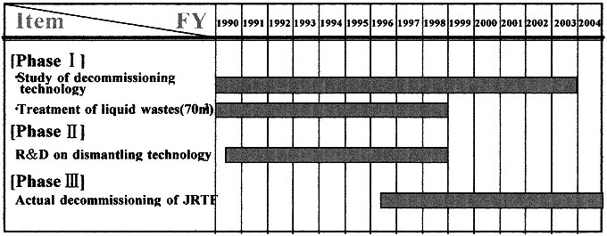
The schedule of JRTF decommissioning program is shown in Table I.
Table I. The Schedule of JRTF Decommissioning Program
STUDY OF DECOMMISSIONING TECHNOLOGY(PHASE I)
In the study of decommissioning technology, radioactivity inventory estimation, dismantling methods, and radioactive wastes generated from dismantling have been investigated for the safe and smooth decommissioning.
The depth of penetrating contamination in concrete was evaluated as less than 10 mm depth from the concrete surface by surveying the concrete core samples which were taken using dry core boring. The total radioactivity remained in the JRTF was estimated to be 2*1010 Bq(a ) and 5*1012 Bq(b g ).
Also, the dismantling methods, dismantling procedure, remote operation techniques, decontamination techniques, etc were investigated in consideration with JRTF’s characteristics.
The total weight of dismantling waste of equipments and concrete was roughly estimated to be 17,000 tons. Radioactive dismantling waste was estimated to be about 425 tons.
About 70 m3 of the liquid wastes from the reprocessing tests were stored in 16 storage tanks. a -contaminated liquid wastes is separated into supernatant and sludge by a coagulation and sedimentation process to remove plutonium. The supernatant is solidfied by the bituminization process and the sludge containing plutonium is vitrified by microwave heating. Unpurified uranium solution is treated by adsorption process using inorganic absorbents(Fibrous Activated Carbon) to remove plutonium. The used absorbent is solidified with cement and canned. The treated solution is solidified with plastic. After removing plutonium by washing with alkaline solution, the spent solvent is treated by the incineration process, and the incineration ash is solidified with cement, canned. About 60 m3 of the liquid wastes were treated so far, and the treatment of the remained liquid will be completed in 1998.
DEVELOPMENT OF DECOMMISSIONING TECHNIQUES(PHASE II)
Three Dimensional Image Drawing System
Decommissioning procedure planning of nuclear facilities has to be based on the latest exact plant data. But sometimes the latest data could not be constructed from the design drawing if several years had passed after the construction and some modification had been made. So, the 3D-CAD system has been developed to image the layout of equipments and to simulate the cutting process and the transportation routes of wastes on the computer. This system is a useful method to estimate the dismantling procedure of the JRTF effectively and precisely.
The 3D-CAD data for the main cell was constructed and this system will be demonstrated in 1998.
REMOTE CONTROLLED PHISICAL DATA ACQUISITION SYSTEM
The remote controlled data acquisition system has been developed for acquiring three dimensional data in high radiation areas where workers cannot access. The concept of this apparatus is shown in Fig. 1. Mobil section consists of the driving mechanism and measuring tools. Driving mechanism has two pair of legs with assist wheel in front side and rear side. Each leg has 2 joints(knee and hip). Two driving wheels are equipped at the center of the body of the driving mechanism. This robot has functions of forward and backward movement, rotation, up and down stairs, striding over pipes. Measuring tools for plant data acquisition consist of an ITV camera for normal view and for close-up view, laser range finder and light. Measuring tools are able to rotate to any direction by a pan and tilt mechanism. The data such as location and size of apparatus and pipes accumulated by this system will be used by inputting to the 3D-CAD system at the actual dismantling.
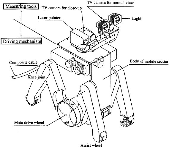
Figure 1. Remote Controlled Data Acquisition System
Mobile Section
REMOTE CONTROLLED DISMANTLING TOOL FOR LARGE-VESSELS
This apparatus has been developed to apply to the dismantling of large vessels. These vessels are contaminated with a -nuclides, and installed in a narrow cell complicated with vessels, pipes and other equipments. The apparatus has multiple functions including decontamination, dismantling of vessels and pipes, and transferring of dismantling wastes, etc. The apparatus consists of five-axis(x, y, z, f , q ) movement system, remote exchange device, maintenance system, cut pieces transfer system, and a remote control system. These functions can be performed in a fully remote manner. Decontamination of the inner surface of the vessels is performed by a high-pressured water jet using 3D-nozzle. Dismantling of the vessels is performed by using plasma cutting and grinder cutting devices, and cutting of connecting pipes is performed by a grabbing and shearing device. Cut pieces are collected by a vacuum pad device. Each head of the decontamination device and cutting devices, etc is fixed and detached by a remote exchange device. These collected pieces are transferred and packed by the cut piece transfer system.
The mock-up test will be performed with a sham tank, and this apparatus will be demonstrated in 1999. The concept of the apparatus is shown in Fig. 2.
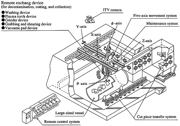
Figure 2. Remote Controlled Dismantling Tool Large-vessels
PROTECTIVE SUIT FOR ALPHA CONTAMINATION
There are some high radiation areas contaminated with a -nuclides in the JRTF. So, the development of protective suit has been carried out to improve protective efficiency for radioactivity, safety and workability. The developed suit has some features, namely expansion of visibility, selection of good heat/fireproof cloth material, exchangeable gloves and boots with consideration for lower cost. The protective efficiency for radioactivity is increased by 104. This suit will be demonstrated in 1998.
LASER DECONTAMINATION FOR CONCRETE SURFACE
The concrete surfaces at the JRTF are contaminated by radioactive material including a -nuclides. The maximum penetration depth of the contamination is about 10 mm. It is necessary to remove the contaminated concrete effectively with consideration for decreasing of wastes, and to reduce the worker’s internal exposure by remote operation. So, the development of a decontamination technique by laser beam has been carried out. A YAG laser was selected because it can be controlled by remote operation using optical fiber and its equipments can be miniacturized.
The decontamination method consists of two processes. In the first method, laser irradiation at low scanning speed is made to cause instantaneous melting of the elements of the concrete(mainly oxides of silicon, aluminum, and calcium) by intense heat, resulting in the formation of a glass layer, which is then removed easily. In the second method, using higher scanning speeds, instantaneous evaporation of the water in the concrete is induced and rapid built-up water vapour pressure occurs without surface melting. This phenomenon causes spalling of the contaminated surface layer. Because the water in the concrete surface is evaporated by spalling, spalling cannot repeat in the same place which is irradiated once. So, glazing is considered to be main method for the actual decontamination.
So far concrete removal tests using YAG laser were carried out changing parameters, such as laser power output, diameter of laser beam and scanning speed. As the results, the suitable conditions were 600 W, 13 f and 80 mm/min for glazing.
The apparatus including remote control unit, collection unit for generated waste, etc is being manufactured. It will be applied to the actual dismantling of the JRTF from 1998. The concept of the apparatus is shown in Fig. 3.
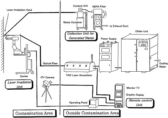
Figure 3. Laser Decontamination System for Concrete Surface
THE ACTUAL DISMANTLING OF THE JRTF(PHASE III)
Phase III is the actual dismantling of JRTF. Decommissioning technologies developed in phase II will be applied to the dismantling activities and the data will be collected systematically to characterize the dismantling activities of the non-reactor nuclear facilities. The major objectives of this phase are to demonstrate dismantling techniques and to accumulate the knowledge and experience for the reprocessing facility decommissioning. The dismantling of equipment, the decontamination of buildings will be performed with consideration for surveillance, the maintenance and the space for temporary waste storage. This project including the demolition of buildings will be completed in 2004.
PhaseIII was started in November 1996, and so far 8 glove-boxes and 2 hoods were dismantled by conventional tools(nibbler and rotary-bandsaw, etc) in the greenhouse. The workers wore airline-suits to prevent internal exposure. Fig. 4 shows the layout of the greenhouse. The waste generated from dismantling were classified into a -contaminated wastes and b (g )-contaminated wastes, and put into 200 liter drums.
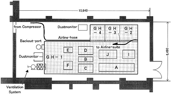
Figure 4. Layout of the Greenhouse
For the dismantling in 1996, the manpower required for the removal of this equipment was 1354 man*days. The collective dose was about 1.1 man*mSv.
a
-contaminated wastes arising from the dismantling activities were cut to small pieces to raise the packing efficiency. As the volume of 8 glove-boxes(21 m3) was reduced to 13 m3, the volume reduction rate was calculated to be 0.62. The total weight of a -contaminated wastes was about 6.7 tons with 96 drums. These drums were stored at the JAERI’s Radioactive Wastes Treatment Facility(JWTF).Before the cutting of glove-boxes, the insides of glove-boxes were decontaminated by the wiping method to decrease radioactivity level. The surface contamination in glove-boxes was fixed with paints to reduce the spread of air contamination during dismantling activities. The maximum surface activity after decontamination was 1.2*102 Bq/cm2(a ), and 1.6*101 Bq/cm2(b g ).
The air radioactivity concentration was continuously measured by a dust monitor during dismantling activities. The maximum air radioactivity concentration in the greenhouse was measured to be 2.4*10-3 Bq/cm3(a ), and 6.7*10-6 Bq/cm3(b g ). Internal exposure for workers was not detected during dismantling activities.
CONCLUSION
The research and development for decommissioning technology in Phase II is making satisfactory progress. These developed technologies will be applied and demonstrated in the actual dismantling of JRTF .
The actual dismantling of JRTF for 1996 was carried out on schedule, and the data and experiences gained from the dismantling of glove-boxes will be utilized in the future decommissioning of JRTF.
The JRTF decommissioning program has been registered with the OECD/NEA Corporation Program on the Decommissioning of Nuclear Facilities, and is proceeding with exchanges of information through international cooperation.