DEFENSE WASTE PROCESSING FACILITY
RADIOACTIVE OPERATIONS - YEAR TWO
J. T. Carter, R. E. Edwards, J. E. Occhipinti, R. S. Beck and D. C. Iverson
Westinghouse Savannah River Company
Aiken, SC 29808
ABSTRACT
The Savannah River Site's Defense Waste Processing Facility (DWPF) near Aiken, SC is the nation's first high-level radioactive waste vitrification facility. This waste (130 million liters) which has been stored in carbon steel underground tanks and is now being pretreated, melted into a highly durable borosilicate glass and poured into stainless steel canisters for eventual disposal in a geologic repository. Following a ten-year construction period and nearly three-year non-radioactive test program, the DWPF began radioactive operations in March 1996. The first nine months of radioactive operations have been reported previously. As with any complex technical facility, difficulties were encountered during the transition to radioactive operations.
Results of the second year of radioactive operations are presented in this paper. The discussion includes: feed preparation and glass melting, resolution of the melter pouring issues, improvements in processing attainment and throughput, and planned improvements in laboratory attainment and throughput.
PROCESS/PRODUCT OVERVIEW
The radioactive waste in the Savannah River Site (SRS) Tanks Farms has been separated into a water soluble salt solution and saltcake, and an insoluble sludge of metal hydroxides and oxides. The salt solution and saltcake are decontaminated for disposal as low-level radioactive waste by the addition of sodium tetraphenylborate to precipitate the soluble salts of non-radioactive potassium and cesium and the addition of sodium titanate to adsorb residual strontium and plutonium. The resulting slurry is filtered and the decontaminated filtrate is blended with cement, slag and flyash for disposal at SRS as a low-level radioactive waste. The sludge portion of the waste is washed to remove soluble salts. If necessary, insoluble aluminum is removed through high temperature caustic dissolution. Thus the radioactive waste from the SRS Tank Farms is transferred in two forms: Precipitate Slurry and Sludge Slurry. Sludge Slurry transfers began in March 1996. The waste is then processed and blended in the DWPF before it is vitrified, poured into canisters, sealed and placed in the Glass Waste Storage Building (GWSB) for interim storage.
The precipitate is processed in the DWPF Salt Processing Cell (SPC) to remove most of the organic material. The tetraphenylborate compounds comprising the precipitate react in the presence of formic acid and copper(II) catalyst. The products of this reaction are aromatic organic compounds (benzene, phenol, and minor amounts of higher boiling aromatics) and an aqueous phase known as Precipitate Hydrolysis Aqueous (PHA). The PHA contains the cesium, soluble formate salts, boric acid and excess formic acid. Since the radioactive precipitate is not yet available for immobilization, simulated PHA (consisting of formic acid, water and soluble copper nitrate) has been substituted.
The sludge is transferred directly into the Sludge Receipt and Adjustment Tank (SRAT) and then neutralized with nitric acid. The simulated PHA is then added to the sludge (at boiling). After the PHA and sludge are blended and processed in the SRAT, this SRAT product is transferred to the Slurry Mix Evaporator (SME) where a borosilicate glass frit is added and the slurry is concentrated to produce melter feed.
The amount of sludge and PHA to be blended in the SRAT and the amount of SRAT product and frit to be blended in the SME is determined by the desired glass composition. This region of desired composition is determined by a series of glass property models and statistical algorithms. Any point within the acceptable region can be selected the target for a particular batch.
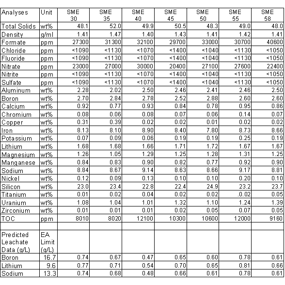
The SME is the hold point in the process. The analysis of SME samples are used by the DWPF engineers to determine the acceptability of the batch versus the Waste Acceptance Product Specifications (WAPS)1. The most important of the glass specifications is the product consistency specification which states that the DWPF must control its process so that the glass produced is more durable than the DWPF Environmental Assessment (EA) Glass2 as measured by the Product Consistency Test (PCT) . The PCT is a crushed glass durability test in which the results are expressed as the amount of boron, lithium, and sodium measured in the leachate. The key glass property model uses the SME composition and a thermodynamic hydration approach to predict the leach rates for boron, lithium, and sodium. Acceptance is based on this prediction. No material is transferred from the SME to the Melter Feed Tank (MFT) until it has been determined to be acceptable. A glass pour stream sample is taken occasionally during filling of a canister to confirm that the glass durability (as determined by the PCT3) is acceptable (see Table I). The characterization of the glass currently being produced at the DWPF is presented in Reference 4.
Once the melter feed material in the SME is determined to be acceptable, it is transferred to the MFT and then fed to the joule heated melter. The DWPF melter has two pairs of diametrically opposed electrodes. The feed slurry is introduced from the top of the melter and forms a crust, or cold cap, on the surface of the melt pool as the water is evaporated and removed via the off-gas system. The cold cap melts from the bottom and forms a borosilicate glass matrix. The nominal glass pool temperature is 1130°C. The mixing behavior of the glass is that of a continuous stirred tank reactor.5 The glass is removed from an opening near the bottom through a riser and pour spout. A vacuum is drawn on the pour spout to pour the glass.
After a canister is filled, a temporary seal is installed to prevent free liquid from entering the canister during the decontamination process. Decontamination of the canister surface consists of blasting an air injected frit slurry against the canister. The frit slurry from decontamination is used in the next SME batch as part of the required frit addition. The canister is then welded closed and transferred to an interim storage building via the Shielded Canister Transporter (SCT).
PRIOR OPERATIONS
Initial DWPF operation is broken down into three sections, Chemical Runs, Waste Qualification Runs (WQR) and Proficiency Runs. Chemical runs produced three feed preparation cycles resulting in sixteen canisters being filled with glass. The feed for this campaign was "Blend" which represented a composite of the SRS Tank Farm waste. This testing was conducted to ensure the facility was ready to begin the WQR.
WQR produced thirteen more feed batches and fifty-five more canisters using feed types representing the expected extremes of the compositional envelope. The extensive product characterization demonstrated that the DWPF complies with the WAPS. 1,5,6 Proficiency Runs were conducted to ensure the operating staff stayed in top readiness while the Operational Readiness Review was conducted and while awaiting the completion of the WQR test results reports. The DWPF processed two additional feed preparation cycles resulting in nine canisters.
During FY-96 the DWPF transitioned from simulated waste to radioactive waste processing a total of eleven feed pretreatment cycles resulting in production of 78 canistered waste forms. 7,8,9 Each canister contained an average of 4000 pounds of glass.
FY-97 OPERATIONS
The first batch of sludge for the DWPF has been washed five times and is currently stored in the H-area Tank Farm Tank #51.
From November 15, 1996 to November 15, 1997, sludge-only radioactive operations continued with the completion of 29 feed preparation cycles (batches SME-30 to SME-58). All 29 feed preparation cycles were produced from a consistent feed stock out of Tank #51. These batches produced 174 glass filled canisters. To date, over 450 metric tones (1 million pounds) of radioactive glass has been poured using Melter #1 and approximately 1 million liters (250,000 gallons) of radioactive sludge waste has been transferred from Tank 51. The SME composition is provided in Table I for every fifth batch produced during this time period. Two of the batches (SME 32, and 38) required remediation to correct an unacceptable glass property.
While processing batch 32, the SME's level instrumentation failed and was boiled at a much higher level than was indicated. Boiling at this high level caused approximately 25% of the solids in the tank to become entrained into the off-gas and subsequently into the condensate tank. Sampling the SME's contents showed that the material lost was homogeneous. This allowed the tank to be remediated with the SRAT product from the upcoming batch and additional frit. The final sample results indicated that batch 32 passed the acceptance criteria.
Batch 38 initially failed on homogeneity (for a discussion of homogeneity see reference 8) and was corrected by the addition of sludge. The batch was re-sampled and passed the acceptance criteria.
Table I. SME Product Analysis
The durability model projected PCT results for every fifth process batch are also given in Table I. Additionally, the published EA glass release results are given for comparison purposes. The projected PCT results for all SME batches were far below the leachate values for the EA glass.11 Based on these results, the glass produced using Tank 51 sludge and Frit 200 is significantly more durable than EA glass and is therefore acceptable (i.e., WAPS requirement 1.3 was satisfied).
Confirmatory glass samples were taken periodically from the glass pour stream and analyzed at the Savannah River Technology Center (SRTC). The results of these tests are discussed in reference 4
PROCESS CYCLE TIME IMPROVEMENTS
Two major process improvements were made during the year. They were: 1) Eliminated the use of the Precipitate Reactor Bottoms Tank (PRBT) in the production of a "simulated" Precipitate Hydrolysis Aqueous (PHA) which was then feed into the Sludge Receipt and Adjustment Tank (SRAT) and 2) Increased the canister decontamination throughput by coordinating the coupled processes of canister decontaminating and SME concentrating.
During the first year of sludge-only radioactive operations, "simulated" PHA made up of copper nitrate, formic acid and water was used during the SRAT process. At that time, this solution was required in the SRAT process to reduce the manganese and mercury oxides as well as destroy the nitrites found in the sludge. Approximately 42,500 liters (11,000 gallons) of "simulated" PHA was required for each SRAT batch. This PHA was made up in two 21,250 liter (5500 gallon) batches and transferred to the SRAT at approximately 30 Lpm (8 gpm) to protect the Safety Analysis basis for controlling the flammability content in the vessel's off-gas. Each batch of solution required sampling that took an average of 12 hours to analyze. A laboratory study was initiated to determine if concentrated formic acid and copper nitrate could be added directly to the SRAT and still maintain the hydrogen generation within the Safety Analysis bases. The noble metal concentration in the sludge is known to be the major catalyst for the decomposition of formic acid into hydrogen. The noble metal content in Tank 51 is considerably lower than what was assumed in the current technical bases, which allows additional acid to be added. The laboratory experiments showed that the new process' production of hydrogen was well within the Safety Analysis limits. It was determined with the addition of slightly more formic acid eliminated the need to add the copper nitrate to the SRAT. The additional acid ensured the nitrite was destroyed with no impact to the hydrogen generation rate basis. These changes were made part of the technical baseline and then implemented at the DWPF in March 1997. This change eliminated the use of the PRBT as a hold tank, two 12 hour sample analyses of the PRBT per batch, and the 42,500 liters (11,000 gallons) of recycle waste per batch. The SRAT cycle time was shortened by approximately 35%.
Once the SRAT process cycle time decreased by over one third, the SME cycle became the "bottle neck" of the facility. The SME process can be broken down as follows:
The major problem area for the SME process lied in steps 3, 4, and 5. Since the canister decontamination process was coupled to the SME cycle, it was very difficult for the facility not to get "backed up" with canisters. The time it took for a canister to be decontaminated and its frit solution to be transferred and boiled off in the SME was about 12 hours. Brainstorming activities began to determine a way that the decon cycle could either be de-coupled from the SME or its cycle time decreased. All de-coupling ideas would have resulted in a substantial capital investment. The SME cycle time could be improved by coordinating the canister decontamination cycle with the SME boiling cycle so that the two worked simultaneously rather than successively. In other words, the SME would be boiling the entire time during the decon cycle. This eliminated the time for heat up and the time between the start of one operation and the beginning of the next. Now, 3 canisters are being decontaminated and the SME concentrated within a 12-hour period. This change was made with no capital investment and now the SME and Melter have the same cycle time.
MELTER POURING
Glass pouring is accomplished by pulling a vacuum (relative to the melter vapor space) on the canister and pour spout (see Figure 1of reference 8). The glass level increases in the riser and overflows into the pour spout. The glass then travels vertically down the sidewall of the pour spout about 38cm where the wall of the pour spout is cut back to form a sharp "knife edge" and the glass disengages. The glass then freefalls a distance of about 60cm through the canister bellows and into the neck of the canister, and up to 300cm more to the bottom of the canister. Any glass, which comes into contact with the unheated bellows, has a tendency to adhere to the stainless steel surfaces and will lead to build-up sufficient to completely block the flow of the glass. While equipment has been designed and built to remove this build-up, this event is undesirable. Glass contact with the bellows or lower section of the pour spout is known as "wicking".
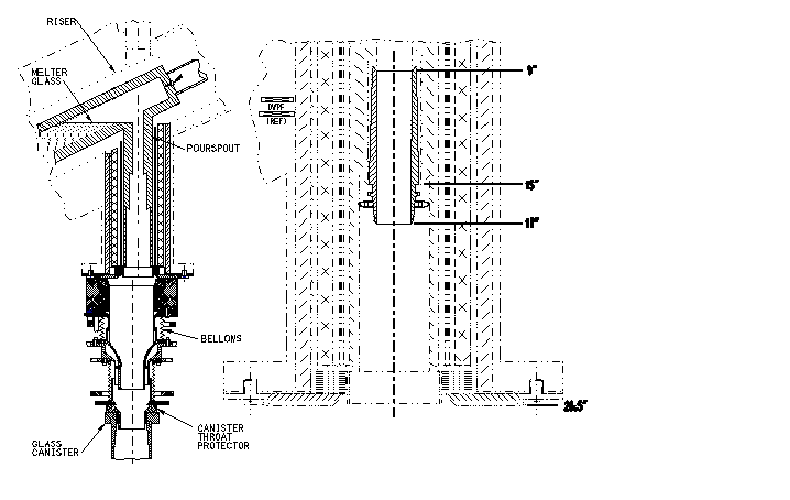
Fig. 1. Melter Pour Spout Configuration at the Start of Radioactive Operations
Prior to beginning radioactive operation, the pour spout was machined to open the lower bore to approximately 4", creating a second "knife edge". See Figure 1. This improved pouring performance but after beginning radioactive operation, pouring behavior continued to degrade and eventually became worse than that encountered prior to machining.
A number of factors were evaluated and adjusted, where possible, in an effort to mitigate the problem. Among these were:
Optimization of several of these variables resulted in some improvement but it became evident that a change to the physical configuration of the pour spout would be needed. A decision was made to develop a remotely installed, replaceable "insert" to be placed in the pour spout to lower the glass disengagement point, to maximize the radial distance from the disengagement point to the lower wall, and provide a fresh new disengagement point. An insert was developed (Figure 1) which is retained in the pour spout by a ring and pin assembly. It was designed to be installed or removed via a telerobotic manipulator, which was installed to facilitate recovery from pour spout pluggage.
Prior to installation in the DWPF melter, the insert was tested in an 1100o C mockup of the DWPF pour spout. The testing showed that the insert could be reliably installed, retained and removed. The insert could resist as much as 140lb of downward force before being forced out of the pour spout.
After thoroughly cleaning and gauging the pour spout the first insert was successfully installed on May 10, 1997. An attempt, immediately after installation, to inspect the installation using a high temperature borescope resulted in binding the borescope within the insert and removal of the insert. A second installation three days later was also successful and glass pouring was initiated. No wicking of the pour stream was noted.
DWPF canister production rate increased significantly after installation of the insert. See Figure 2. This in conjunction with process improvements allowed DWPF to exceed its production goals for FY97 by 19 canisters. (Projections prior to insert installation were to fall far short of the goal.)
As a result of this experience, the design of future DWPF melters is being revisited to incorporate similar improvements. This includes modification of pour spout clearances and location of glass disengagement point and to incorporate a remotely replaceable disengagement point (knife-edge).
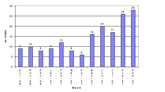
Fig. 2. FY-97 Canister Production
FUTURE IMPROVEMENTS
The (DWPF) has performed elemental determinations on mixtures of sludge, frit and water by Inductively Coupled Plasma Atomic Emission Spectroscopy (ICP-AES) since the early 1990's. The steps leading to elemental determinations involves sampling the process tanks, preparation of the slurry sample in shielded cells and ICP-AES analysis in a hood. The analytical process has remained essentially unchanged throughout startup and radioactive operation. Changes to sampling and analytical preparations have been identified as potential improvements to the analytical process.12 The plant process is improved by reducing the time associated with delaying the transfer of the Slurry Mix Evaporator (SME) pending analytical results.
The contents of the process tanks are sampled with a recirculating loop that contains a side stream HydragardTM sampler. The side stream flows through a glass vial that is sealed with a viton septum. This sampler configuration has been verified through startup and qualification tests to provide a sample representative of the tank contents.
A 3 ml container was tested as a means of reducing the sample size submitted for analytical preparation allowing consideration of alternative methods. The smaller sample container was evaluated during a series of tests in the summer of 1997. The testing was performed using a HydragardTM sampler system located in a mockup of the analytical shielded cells. A small scale sampling system fitted with a HydragardTM was installed in the mockup. A non-radioactive slurry which had been used previously at a pilot facility to model the DWPF process was used for the test.
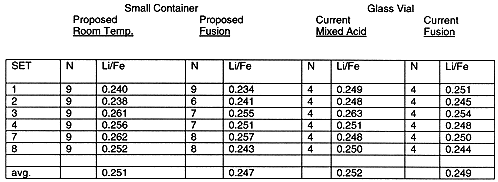
The evaluation of the small sample container was accomplished in part using the ratio of two key elements from the slurry composition. Iron providing a major sludge component and lithium a unique component found in frit. The ratio of the two elements from the ICP-AES analyses provided detection of slight shifts in the composition of the slurry. Table II lists the lithium to iron ratios for the testing. The lithium to iron ratios clearly support that the two containers may be interchanged without impacting the composition of the sample for elemental analyses.
Table II. Lithium: Iron Ratios-Small Container Compared to Glass Vials
The conventional preparation used at DWPF for elemental analyses involves a series of steps designed to stabilize and homogenize the slurry sample. Since beginning radioactive operations the total analytical time has been decreased by gains in laboratory efficiency from 60 hours to about 35 hours for sludge/frit/water solutions contained in glass vials. Any further improvements require changes to the analytical method. A cost-effective approach is possible with the use of small sample containers, specifically direct slurry dissolution. By using the smaller container, the sample contents can be transferred along with the sample container into a dissolution vessel ensuring quantitative transfer of the sample. The steps to stabilize and homogenize the sample, drying, vitrification and grinding, are eliminated by this approach. This is projected to provide the means to achieve a total analytical time of 12 hours to 20 hours rather than 35 hours.
Two Analytical methods were tested at DWPF, room temperature acid dissolution and a modified alkali fusion to replace the current methods.
The proposed acid dissolution is a mixture of hydrofluoric and nitric acids at room temperature replacing a mixed acid microwave assisted method. In the proposed method a TeflonTM insert containing the sample was placed into a wide mouthed plastic bottle. The acids were added in sequence to dissolve the sample. Compounds of aluminum, magnesium and calcium tended to form a fine precipitate. The proposed method did not use boric acid to complex the fluoride as is the case with the current mixed acid method. However, upon additional dilution the salts dissolved and the solution was analyzed by ICP-AES for all elements of interest to the DWPF process.
The proposed alkali fusion is a sodium peroxide/sodium hydroxide method. The alkali fusion method is already in use at DWPF but was modified for the use of a small container made of high purity zirconium. The sample material in the zirconium container was transferred into a zirconium crucible. Water was driven off by drying at 115oC followed by partially conversion (calcine) of the dried sample to oxides by heating to 600oC . The calcined sample was dissolved (fused) in a pool of molten alkali peroxide/hydroxide. The resulting fusion was dissolved with water and acidified with hydrochloric acid. The acidic solution was then analyzed by ICP-AES for all elements of interest except for sodium. Consequently, the fusion method is considered a supplement.
Six blocks of activity comprised the comparison of the proposed analytical methods to the current analytical method. Each block involved sampling, preparation of the samples and elemental analysis. The overall results are listed in Table III. The room temperature results and modified fusion results were converted to a glass basis for comparison to the current method. Generally there was good agreement between the conventional (mixed acid, fusion) and proposed methods (room temp, modified fusion).
Table III. Sample Preparation Test Results
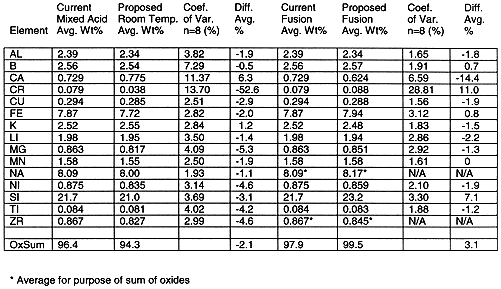
On a glass basis, the sum of the oxides provides a measure of recovery. The sum of oxides for the room temperature analytical method was slightly lower than the mixed acid analytical method (94.3 % vs. 96.4%). The modified fusion analytical method was slightly higher than the current fusion analytical method (99.5 % vs. 97.9 %).
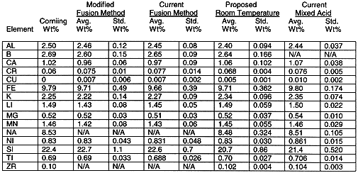
Analytical Reference Glass powder (ARG-1) was tested along with the simulant. The glass powder was developed through a round robin program coordinated by the Materials Characterization Center (MCC) at Pacific Northwest Laboratory (PNL). The results were compared to reference values in Table IV. Lower than expected results were noted for the silicon analyses of the ARG-1 prepared by room temperature dissolution. There was 13 replicates for the Current Mixed Acid analyses and 12 for the remaining.
Table IV. ARG-1 Test Results
CONCLUSION
In summary, the DWPF has begun the task of vitrifying radioactive waste into a borosilicate glass. Through November 15, 1997, DWPF has produced 252 canistered waste forms, which meet the USDOE requirements for long term disposal in a geologic repository.
Some major process and melter pouring improvements this year allowed DWPF to exceed its canister production goal. These improvements where to the melter feed preparation cycle time and the development of a removable pour spout insert. Future improvements to the facility are centered around the laboratory analytical methods. The improvements are directed toward saving time during coupled (precipitate + sludge) operations. At the present canister production rate, the DWPF will vitrify the first batch of sludge waste in Tank 51 (~1.5 million liters) by the end of FY98.
ACKNOWLEDGEMENT
This paper is a tribute to the many individuals who worked to make the radioactive operation of the DWPF a reality.
This paper was prepared in connection with work done under Contract no. DE-AC09-89SR18035 with U. S. Department of Energy.
REFERENCES
1. Office of Environmental Management, Waste Acceptance Product Specifications for Vitrified High-Level Waste Forms, Rev1, USDOE Document EM-WAPS, U.S. Department of Energy, Germantown, MD (1995).
2. U. S. Department of Energy, Environmental Assessment - Waste Form Selection for SRP High-Level Waste, USDOE Document DOE/ES-0179, Washington, DC (1982).
3. "Standard Test Methods for Determining the Chemical Durability of Nuclear Waste Glasses: The Product Consistency Test (PCT)," ASTM Test C1285-94, pp. 797-812 in 1995 Annual Book of ASTM Standards Vol. 12.01, Philadelphia, Pa., 1995.
4. J. W. RAY, N. E. BIBLER, T. R. FELLINGER, O. B. HODOH, R. S. BECK, and O. G. LIEN, "Characterization of the Radioactive Glass Currently Being Produced by the DWPF at Savannah River Site", Proceedings - Waste Management '98, CD-ROM Session 14.
5. S. L. MARRA, D. E. SNYDER, H. H. ELDER and J. E. OCCHIPINTI, "The DWPF: Results of Full Scale Qualification Runs Leading to Radioactive Operations", Proceedings - Waste Management '96, CD-ROM Session 8-2.
6. S.L. MARRA and M. J. PLODINEC, "The DWPF Waste Qualification Program", Proceedings -Spectrum 94, Nuclear and Hazardous Waste Management International Topical Meeting, American Nuclear Society, La Grange Park, IL, 1496-1501 (1994).
7. D.B. LITTLE, J.T. GEE, and W.M.BARNES, "Defense Waste Processing Facility Radioactive Operations -Part I , Operating Experience", Proceedings - Waste Management '97, CD-ROM Session 14.
8. J.T. CARTER, K. J. RUETER, J. W. RAY, and O. B. HODOH, "Defense Waste Processing Facility Radioactive Operations -Part II , Glass Making", Proceedings - Waste Management '97, CD-ROM Session 14.
9. W. D. KERLEY, W. M. BARNES, and P. D. HUGHES, "Defense Waste Processing Facility Radioactive Operations -Part III - Remote Operations", Proceedings - Waste Management '97, CD-ROM Session 14.
10. J. T. CARTER, K. G. BROWN, AND D. F. BICKFORD, "DWPF Glass Composition Control Based on Glass Properties," Proceedings - First International Conference on Advances in the Fusion of Glass, D. F. Bickford, et al. (ed.), American Ceramic Society, Westerville, OH, (1988).
11. C. M. Jantzen, N. E. Bibler, B. C. Beam, C. L. Crawford, and M. A. Pickett, "Characterization of the Defense Waste Processing Facility (DWPF) Environmental Assessment Glass Standard Reference Material", WSRC-TR-92-346, Rev. 1, Westinghouse Savannah River Co., Aiken, SC, 1993.
12. C. J. Coleman, N. E. Bibler, D. M. Ferrara, and M. S. Hay, "Analysis of High-Level Radioactive Slurries as a Method to Reduce DWPF Turnaround Times" Proceedings- Environmental Issues and Waste Management Technologies in the Ceramic and Nuclear Industries II, American Ceramic Society, Westerville, OH (1996)