VERTICALLY-ORIENTED GAS-DRIVEN
HYDROFRACTURE AT WIPP
Walter Gerstle, Associate Professor
e-mail: gerstle@unm.edu, phone: (505)277-3458
Robert Valerio, Graduate Student
e-mail: rvalerio@arc.unm.edu, phone: (505)877-2486
Department of Civil Engineering,
University of New Mexico
Albuquerque, NM 87131
ABSTRACT
Modeling and experiments performed by Sandia National Laboratories show that gas caused by the anoxic corrosion of iron and by biodegradation of organic materials will be generated within the Waste Isolation Pilot Plant (WIPP). A potential exists for several tens of million cubic meters (at atmospheric pressure and 30oC) of gas to be generated. A review of the WIPP Compliance Certification Application (CCA) calculations and associated literature has revealed inadequate consideration of gas-driven hydrofracture. This paper presents the results of both laboratory modeling and mathematical analysis of gas-driven hydrofracture at WIPP, with emphasis upon the behavior of a vertical hydrofracture. The results show that unless special care is taken to preclude the generation of gas or to properly vent gas, a gas-driven hydrofracture is likely. Our physical modeling reveals the development of both horizontally- and vertically oriented circular hydrofractures, even within a horizontally stratified solid. The behavior of a vertical hydrofracture is considered in this paper. It is shown that a vertical hydrofracture would be incapable of containing the gas volumes predicted. A novel method is proposed for controlling the build-up of waste gas within the repository so that the hypothesized hydrofracture events will be avoided.
INTRODUCTION
Performance Assessment Verification Tests (PAVT) performed by Sandia National Laboratories, using a two-phase flow, nonlinear variable porosity/permeability model show, apparently incorrectly, that gas generated at the Waste Isolation Pilot Plant (WIPP) will be adequately contained(1). The gas is caused by the anoxic corrosion of iron and by biodegradation of organic materials in the waste. Depending upon the scenario, volumes of gas generated are expected to be on the order of from 10x106 m3 to 30x106 m3 (at atmospheric pressure and 30oC)(1). A review of the WIPP PAVT and Compliance Certification Application (CCA) calculations and associated literature has revealed inadequate consideration of gas-driven hydrofracture(2,3). This paper presents the results of both laboratory modeling and mathematical analysis of gas-driven hydrofracture at WIPP, with emphasis upon the behavior of vertical hydrofractures.
Linear Elastic Fracture Mechanics (LEFM) has been used for predicting the behavior and extent of horizontal, circular, hydrofractures at WIPP induced by various causes(3,4,5,6,7). We have recently performed laboratory hydrofracture experiments, following upon the work of Valerio et al.(8), that show that hydrofractures may sometimes propagate in directions other than horizontal, despite horizontal bedding planes. Some of these hydrofracture experiments are documented in this paper.
If, as our experiments indicate, it is possible for vertical hydrofractures to develop, even in horizontally bedded salt formations such as the Salado where WIPP is located, then it would seem prudent to analyze the behavior of a vertical hydrofracture. A mathematical LEFM analysis of a vertically oriented, circular hydrofracture is presented here. This analysis shows that a vertical hydrofracture at WIPP is capable of growing to only a reasonably small radius, and can contain only a small volume of gas. Once this critical crack radius is exceeded, the crack will unstably propagate vertically to the ground surface, as a finger twice the width of the critical crack radius, producing a flow conduit between the repository and the ground surface.
We must conclude, therefore, that gas pressures at WIPP must not be allowed to build up to the point where hydrofracturing becomes possible. We discuss several options for preventing such hydrofractures at WIPP.
EXPERIMENTAL SETUP
Laboratory hydrofracture experiments of colored fluid in gelatin have been previously described in Valerio at al.(8). In ongoing experiments, the laboratory setup has since been improved upon. The experimental apparatus shown in Fig. 1 uses a network of pipes to conduct fluid from a storage reservoir to a cylinder where the flow rate of the pressurizing fluid (colored water) is controlled by a piston. The piston is pushed by a threaded rod, which is turned at a rate of two revolutions per minute by an electric motor. The piston forces the fluid at a rate of 1.09 milliliters/revolution into a small pipe that conducts fluid into the gelatin tank containing the hydrofracture. Thus, fluid enters the hydrofracture at a rate of 0.03633 ml/second. The pressure is measured in the pipe between the piston/cylinder and the hydrofracture by a pressure transducer. The electrical signal produced by the pressure transducer is amplified and sent to an X-Y pen plotter, which records pressure vs. time. The range of the transducer is 0 to 10 psi. When desired, the fluid can be routed to an analog pressure meter for calibration of the X-Y plotter.
The piping system is constructed of stainless steel .25 in. (6.35 mm) outside diameter pipes with valves for calibrating and bleeding the system. The piping feeding from the control cylinder into the experimental chambers consists of 0.025 in. (0.635 mm) inside diameter stainless steel and copper tubing.

Fig. 1. Photograph of Experimental Apparatus.
A Plexiglas plate partitions the gelatin tank into two separate testing chambers of equal size. Valves control the fluid to flow into either one chamber or the other, allowing one test to be performed at a time. Each chamber has a vertical .025 in. (0.635-mm) inside diameter stainless steel pipe raising from its floor. The colored fluid enters this pipe and causes the hydrofracturing of the gelatin at its top. During the testing phase of the experiment a thumbtack is inserted loosely into the stainless steel pipe to prevent gelatin from clogging the pipe, and also as a mechanism to initiate the hydrofracture in a horizontal plane.
Test Preparation
Prior to running the hydrofracturing tests the testing tank and piping network must be set up properly and calibrated. The procedure for setting up each test is as follows:
The following process is performed to calibrate the data acquisition system and to conduct the test:
C
) Attach the drive motor to the threaded rod that drives the piston.C
) Select a chamber to test and open the valve that goes to the chamber.C
) Begin the X-Y chart recorder.C
) Start the video cassette recorder to record the crack behavior as a function of time.C
) Turn on the motor to begin the test. Take 35mm photos of the hydrofracture.Experimental Results
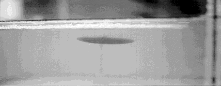
Approximately 30 tests have been run over the last year and many different hydrofracture behaviors have been encountered. It was initially expected that a horizontal hydrofracture would be initiated and that it would propagate axisymmetrically, dishing gradually upward as it propagated, as shown in Fig. 2(a), until either it encountered a free surface or was trapped by a horizontal plane of weakness. This behavior occurred only occasionally, despite the thumbtack,

Fig. 2(a). Example of Horizontal Hydrofracture.

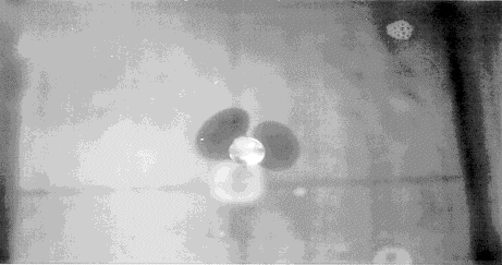
Fig. 2(b) - Example of Two Hydrofractures Oriented at 45-Degrees and 30-Degrees.

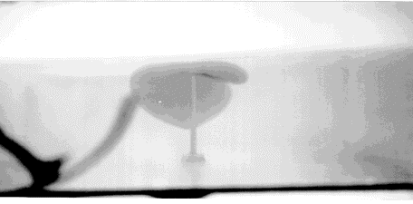
Fig. 2(c) - Example of Vertical Hydrofracture.
which was intended as a guide to produce horizontal crack initiation. In just as many tests, vertical and off axis (30-45 degrees) cracks initiated and propagated. Apparently, the direction of crack initiation was random, and depended upon small differences in the initial conditions close to the site of nucleation, over which we had no control. Fig. 2(a) shows an example of a hydrofracture that initiated in a horizontal plane. This crack then propagated axisymmetrically gradually upward, until it ultimately broke through the top surface of the gelatin, expelling the fluid.
Hydrofractures that initiated at approximately 45-degree angles from horizontal have also been frequently encountered. Often, the crack initiated in a downward direction from the thumbtack, and eventually propagated toward the surface. Fig. 2(b) shows a photograph of an experiment with two cracks that formed at different angles. One is oriented at around 45-degrees, and the other is oriented at a more shallow 30-degrees.
Finally, vertical hydrofractures are not the most common encountered but have been seen in several experiments. The experiment shown in Fig. 2(c) had a layer of gelatin above the top of the vertical pipe. This would cause an in increase in hydrostatic pressure on the initial crack and may have been the cause of the vertical crack initiation.
FRACTURE MECHANICS ANALYSES
Analytical modeling of the propagation of a horizontal circular hydrofracture has been developed and reported in Gerstle and Bredehoeft(3), which provides background for the derivation of the following equations, which relate fluid pressure, crack opening displacement, and fluid volume to hydrofracture radius, predicted using LEFM.
|
|
|
|
|
|
|
|
|
Where
Vcrack is the volume of fluid enclosed by the hydrofracture (variable)
p is the fluid pressure in the hydrofracture (variable)
g
is the density of the overburden (taken as 0.02246MN/m3)D
is the maximum crack opening displacement (at crack center - variable)a is the radius of the hydrofracture (variable)
d is the depth of the hydrofracture center (taken as 659 m or variable).
E is Young=s Modulus of halite (taken as31000 MPa);
v is Poisson=s Ratio of halite (taken as 0.25);
KIc is the fracture toughness of anhydrite (taken as 0.5 MPa-m1/2);
We now derive analytical equations for the propagation of a vertically oriented hydrofracture at WIPP. In this analysis, the assumption is made that the hydrofracture is circular in shape, with radius, a, small compared to its depth of embedment, d, and subject to a far-field hydrostatically increasing equivalent fluid pressure with constant density, g , as shown in Fig. 3. The crack is subject to uniform internal gas pressure, p.

Fig. 3. Schematic of Vertically-Oriented Circular Crack.
The analytical solution for this crack can be found by superimposing exact analytical solutions found in a handbook of stress-intensity factors(9). The expression for stress-intensity factor, KI and crack volume, Vcrack are found to be
|
|
|
|
|
|
|
|
|
where y is the distance above the crack center, and s is the distance from the crack center to the ground surface, as shown in Fig. 3. The stress-intensity factor is not uniform along the crack front, and it attains a maximum at the top of the crack. Assume the crack will propagate when the stress-intensity factor, KI, anywhere along the crack front becomes equal to KIC. Thus the crack would propagate preferentially on its topside and would tend to grow into a non-circular, "egg-shaped" crack. Nonetheless, we assume that the crack remains circular as it grows, as no analytical solutions exist for "egg-shaped" cracks. The maximum value of KIc occurs at y=a. Therefore, it is reasonable to assume that the bottom of the crack will not propagate downward, while the top of the crack front will propagate upward. If we assume that the starting crack, with radius a0, is located with its lower side at the elevation, d, of the repository, then s is equal to d minus a in Eqs. (4). (5), and (6) above.
Assume that the crack propagates when KI(y=a) = KIC. Thus, from Eq. 4, we have
|
|
|
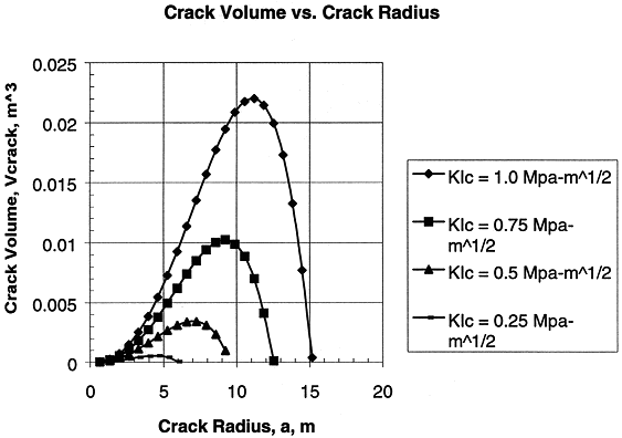
By substituting p from Eq. (7) into Eqs. (5) and (6), we develop analytical functions for p, D center, and Vcrack as functions of crack radius, a. Fig. 4 shows Vcrack versus a for four different assumed values of KIc (otherwise, all parameters take the values shown in the list of definitions above). Perhaps surprisingly, at some critical value of a, Vcrack reaches a maximum value, after which the equilibrium volume enclosed by the crack begins to decrease with increasing crack length. This can be explained by the fact that the pressure, p, necessary to propagate the crack decreases quite rapidly with increasing radius, while the average closing pressure, g s, decreases much less rapidly. (Note that the expression for volume is actually underestimated, perhaps by a factor of 2 or 3, as interference between the two crack faces near the bottom of the crack prevents overlap.)

Fig. 4. Crack volume Vcrack, versus Crack Radius. a.
Once this critical volume of gas has filled the crack, the crack is predicted to begin to grow rapidly at its topside, while the bottomside of the crack will close (and probably heal over time). Thus, the nature of the growth of vertical cracks is dendritic and dynamic, with a single finger of a width that is relatively small. As the crack propagates upward, its width will increase because of the decreasing lithostatic pressure and the corresponding increase in crack volume predicted by the ideal gas law.
CONCLUSIONS
We have shown through laboratory testing, as a consequence of fluid pressure in excess of lithostatic in a solid medium, that in addition to horizontal hydrofractures, vertical hydrofractures can develop. It appears that the direction of hydrofracture initiation is very sensitive to local conditions at the site of nucleation. The behavior of horizontal hydrofracturing at WIPP has been described in previous papers. In this paper, the behavior of a vertical hydrofracture is modeled using LEFM.
We find, perhaps surprisingly, that a vertical hydrofracture within a solid medium subject to a hydrostatically increasing lithostatic stress field can grow only to a certain critical size that is a function of the fracture toughness, KIc, after which the crack will propagate upward in an unstable manner. Thus, the crack "fingers" upward, until it reaches the ground surface. Under the conditions that obtain at WIPP, the width of such a finger is approximately 7 m. Thus, a new mechanism has been identified that can hydraulically connect the repository to the surface environment.
Both horizontal and vertical cracks propagate at approximately the lithostatic pressure at the depth of the topside of the crack. The lithostatic pressure is minimum at the topside of a vertical crack that grows upward from a horizontal crack. Thus, if a horizontal crack intersects an initial vertical crack, the vertical crack is likely to grow unstably toward the ground surface, reducing the fluid pressure and therefore arresting further growth of the horizontal crack This mechanism has not been previously considered.
Obviously, the original concept of WIPP as "impermeable envelope" for containing nuclear waste becomes highly questionable under the scenario of generation of waste gases. To preclude hydrofracture development, so that WIPP can function as intended, gas pressures must never be allowed to reach lithostatic levels. Because of the existence of brine in the rock salt, there is a potential, if not likelihood, for anoxic corrosion of the iron within the waste, with attendant build up of gas pressure. It therefore seems essential either to vent such waste gases in a controlled way, or to prevent them from occurring in the first place.
One possible approach to preventing the undesirable and somewhat unpredictable consequences of gas-driven hydrofracture at WIPP is to allow the materials to corrode and to degrade to low chemical potential prior to sealing the repository. Perhaps, first emplacing the waste barrels within the repository, and then adding brine or other chemicals can accelerate the waste degradation, with attendant gas generation. If the waste materials can be brought into chemical equilibrium with their halite surroundings within a few years, then the potential for subsequent gas generation would not exist, and WIPP would perform in accordance with its original philosophy.
ACKNOWLEDGMENTS
The financial support provided by the Waste Management Education and Research Consortium (WERC); the Center for Autonomous Control in Engineering (ACE); and National Science Foundation Award No. EEC-9322063 is gratefully acknowledged.
REFERENCES