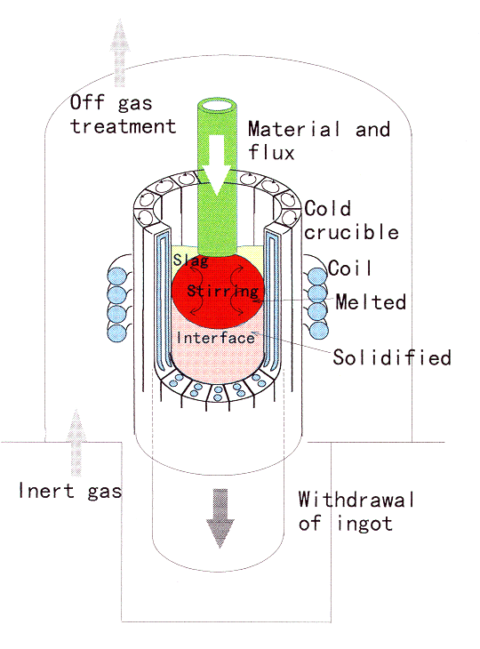
Fig.1. Schematic view of the
fundamental experimental apparatus.
Masahiro Suzuki, Kunisuke Tsurumaki and Junji Komatsu
Research Association for Nuclear Facility Decommissioning(RANDEC)
821-100,
Funaishikawa, Tokai, Ibaraki, Japan
Tsutomu Tanaka and Yoshiaki Ikenaga
Corporate Research Labs.,Sumitomo
Metal Ind. Ltd. (SMI)
16, Sunayama, Hasaki, Kashima, Ibaraki, Japan
Hiroshi Nose
Sumitomo Metal Technology Ind. Ltd.(SMT)
1-1-3,
Otemachi,Chiyodaku, Tokyo, Japan
ABSTRACT
An induction cold crucible melting is one of the most promising technologies for the reuse of radioactively contaminated metals because it ensures a long life operation without generating secondary wastes under the high temperatures of metal melting.
A feasibility study on MERC (Melting and Recycling of Metals by Cold Crucible) process has been recently finished in RANDEC. In MERC, an induction cold crucible, which mainly consists of a melter, decontaminator and continuous caster is used for the melting and recycling of metals contaminated by low level radiation with small section generated from the nuclear facilities.
A cylindrical ingot of 3kg and 45mm in diameter was continuously cast by the MERC process through melting and solidifying simulated radioactive metallic tubes with the addition of flux composed of lime, alumina and silica. Neither splash of the melt nor increase in the temperature of the hook supporting tubes took place during releasing the tube onto the melt dome. The ingot surface was smooth and crack free, promising removal of radioactive elements contained in a slag stuck to the ingot surface. There was no macro segregation inside. Tracer elements of Sr and Hf remained in the slag, Cs and Zn in the dust. Co and Mn mostly remained in the ingot. However, up to 10% of Co could be transmitted to the slag.
Necessary data in the scheduled scale-up of MERC process was obtained through experiment as well as theoretical study. These results are transferred to the design and manufacturing of testing apparatus.
INTRODUCTION
A variety of melting tests have been conducted in various countries, including Japan, in order to develop technology for the reuse of metallic scrap generated during the dismantling of nuclear power plants or the replacement of such equipment(1,2,3). Of such technologies, most of the melting was done in a vessel surrounded with a high temperature wall, such as refractory, and the metal was heated by induction, plasma, etc. However, high temperature walls inevitably leads to the generation of secondary wastes. Only melting in a cold wall furnace can solve such a problem. An induction cold crucible, which is a furnace, stirrer, contact less confinement equipment of the melt and solidifying mold, is one of the most promising technologies. The crucible comprises a water cooled copper wall being segmented as well as electrically insulated by slits, induction coil, withdrawal device, atmospheric chamber, etc.
The crucible has long been used for the melting and casting of chemically active metals with high melting temperatures, such as titanium alloy (4). This technique would be applied to the melting and solidifying contaminated scrap in the industrial scale in the course of recent development of high-power, high-frequency technology.
In the present study the following points were investigated through fundamental experiment as well as theoretical study.
This work is a part of the joint project of RANDEC and SMI under the sponsorship of the Science and Technology Agency of Japan.
EXPERIMENTAL METHOD
Quality of the Ingot
Quality of the ingot plays an important role in the reuse of contaminated scrap. This is not only due to the requirement from the manufacturing of materials but also from the decontamination of nuclides from the scrap. Generally, the nuclide transfers from scrap to ingot, slag, dust, off-gas, etc. and the slag contaminated with nuclides sticks on the surface of the ingot. It would be difficult to remove the slag from the ingot if the ingot has some cracks and slag infiltrates into the crack gaps. As a result, decontamination efficiency would decrease.
Fortunately in the MERC process, shear stress between the ingot and cold wall can be decreased by the electromagnetic pressure working on the ingot and melt surface. Furthermore, melting near the cold wall is promoted by vigorous agitation caused by the inhomogeneous electromagnetic field and high Joule heating. Consequently, a high quality ingot is expected to be cast.
A schematic view of the fundamental experimental apparatus is shown in Fig.1. A water cooled and segmented copper crucible is surrounded with a multi-turn induction coil. After the primary, which is a base metal for the melting, was inserted from the bottom opening to the suitable level for melting in the crucible where the magnetic field is most effective, the atmosphere in the chamber is replaced with Ar gas. With an increase in power input through the induction coil, the primary melts to rise in a dome shape by Joule heating and electromagnetic force. The molten metal experiences electromagnetic stirring and the top of the melt is out of contact with the cold wall, resulting in the increased heat efficiency.
Fig.1. Schematic view of the
fundamental experimental apparatus.
After the primary was melted, tube-shaped raw materials were supplied from the crucible top opening onto the melt dome. Precise velocity control concerning supply of the raw materials and withdrawal of the ingot preserves the dome height at a certain fixed level during continuous melting. As a result, melted and successively solidified ingot is obtained.
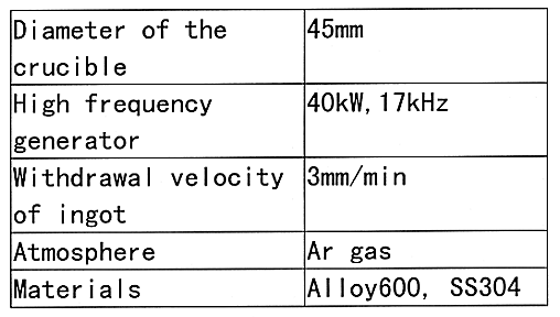
Major experimental conditions are shown in Table I. Withdrawal velocity of 3mm/min corresponds to the tube supply velocity of 46mm/min. Two kinds of materials, Alloy 600 and SS(Stainless Steel) 304, were melted. They were chosen assuming the reuse of steam generator materials of PWR and piping in the nuclear power plants, respectively.
Table I Major Experimental Conditions
Transfer of Tracer
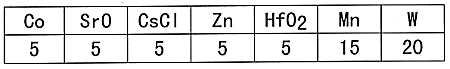
Tracers, which are the simulated radioactive nuclides, were added to investigate the apportionment of nuclides among ingot, slag and dust. The amount of tracers added are shown in Table II. Co, Sr, Cs, Zn and Mn are used as surrogates for those of unstable nuclides. Hf is the surrogate for actinide elements. Measured amounts of tracers are homogeneously filled in the vacancy of the tubes before melting.
Table II Amount of Tracer and Tungsten Added During Melting (g)
To identify the solidification front, tungsten powder was added on the melt dome after the primary was melted. During the melting, flux mainly composed of lime, alumina and silica was added on the melt dome. The melt is almost covered up by the flux to enhance the reaction between melt and slag. Basicity of the flux, which is the dimensionless number of mass of lime divided by that of silica, was changed from 0.3 to 1.8 during the experiment.
Dust was captured by an off gas filter. No special slag collector was used. Slag stuck on the ingot surface was easily removed either by the difference in thermal shrinkage between the ingot and slag or by threshing the ingot after casting.
Melting of Tube Shaped Material
The induction cold crucible method has the property that the cross section of the crucible is small compared with the other conventional induction furnaces with high temperature refractory walls. This means that the long shaped materials, such as piping or tubing, are suitable for melting. For this reason, we selected tubes as the raw material. 4 pieces of Alloy 600 tubes of 7mm in diameter are held vertically by the frictional force with the hooks and descend into the melt dome continuously. At some height, tubes are to be released to fall down on the melt dome to prevent the hooks from melting. When the release height of the tubes is high, temperature of the hooks is low. However, some troubles ,such as splash of the melt or tumbling of the tube, followed by rolling out from the crucible may happen.
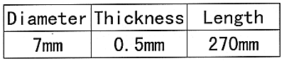
The melting condition for this test is almost the same as Table I except that 4 pieces of Alloy 600 tubes shown in Table III are used.
Table III Dimension of the Alloy 600 Tube
MATHEMATICAL MODELING
A testing apparatus is scheduled to be built after the completion of the fundamental experiment. One of the important design parameters of the testing apparatus is the estimation of the necessary power of the high frequency generator. The dimension of the testing apparatus was determined as 100mm in crucible diameter keeping the melting of several pieces of tubing in mind. In the conventional steam generator of a PWR power plant, 4 pieces of heat exchanger tubes can be melted simultaneously in the testing apparatus.
Necessary and sufficient power for the high frequency generator for the melting of tubing can be estimated by mathematical model (5) aided by the fundamental experimental data. The estimation procedure by the mathematical model is shown in Table IV. First, the shape of the melt dome is estimated. This can be achieved by solving the free boundary problem for the melt shape considering the force equilibrium among electromagnetic pressure, gravity and surface tension by the sheet model of the electromagnetic field, assuming static liquid metal. Note that the model gives an inappropriate result for low power supply, because the material hardly melts under such conditions, whereas the models assumes that the material is liquid. However, this point is substantially unimportant and the method is valid when the input energy is large enough to melt and the skin depth is small compared with the ingot radius.
Table IV Estimation of Scale-up of MERC Process by Mathematical
Model
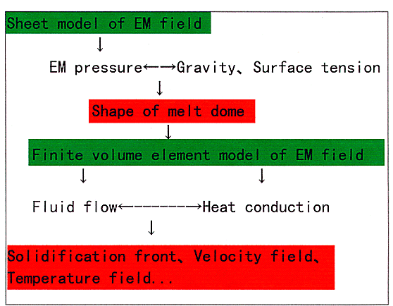
The solidification front is obtained from the coupling of fluid flow with heat transfer as a function of heat transfer coefficient between ingot and cold wall, after the electromagnetic field was obtained by the finite volume element model. A suitable heat transfer coefficient is estimated by the comparison of the solidification front obtained through the experiment with that of calculation. After this, the same heat transfer coefficient is applied to the enlarged MERC process with a parameter of supplied electric power. As a result, necessary and sufficient power for the melting of piping and tubing is determined.
EXPERIMENTAL RESULTS
Quality of the Ingot
Selection of the optimal casting condition concerning dome height, casting velocity and power supply resulted in the production of ingots of 3kg order in the MERC process. Surface and longitudinal section along the withdrawal direction of the typical cast ingot of Alloy 600 material are shown in Fig. 2, respectively. Length and diameter of the ingot are 200mm and 45mm, respectively. Apparently, the surface is smooth and crack free promising that the ingot surface will be free of trapped slag. Actually some of the slag was stripped off automatically by thermal shrinkage after cool-down and some was removed by simply thrashing. Soundness of surface quality facilitates decontamination by the removal of slag containing nuclides.
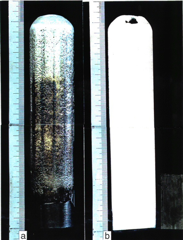
Fig.2. Continuously cast alloy 600
ingot (a: surface, b: longitudinal section).
It is notable that in spite of the presence of slits, the melt hardly infiltrates into the slit gap. The color corresponding to the slit part is a somewhat dark. Generally, the dome shape has periodicity on the periphery just like petals in such a way that the surface in front of the slit corresponds to the gap between petals and is depressed by stronger magnetic field. Change in color would be responsible for the gathering of oxide generated by insufficient air replacement with Ar gas at the periodic melt depression adjacent to the slit. A cavity caused by solidification shrinkage is observed on the end part of casting. However, the influence of the cavity can be minimized by the establishment of complete continuous casting in which a long ingot is produced. Inner quality of the ingot is homogeneous and any non-melted part of the raw material is not observed.
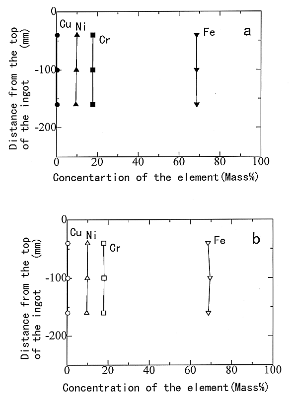
Concerning the surface and inner quality of the ingot, almost the same result as that of Alloy 600 was obtained in the melting of SS304 tubes. The amount of elements Cu, Ni, Cr and Fe were analyzed by Ion Coupled Plasma Spectroscopy (ICPS). Distribution of the elements along the withdrawal direction are shown in Fig.3 on the center and on the subsurface of 5mm distance from the surface, respectively. Concentration of the elements are homogeneous along the longitudinal direction as well as in radial direction. This shows the soundness of the ingot and capability of reuse after radioactivity has decreased less than some allowed value. It also shows that no specific highly contaminated part exits in the ingot, facilitating safekeeping of ingot for some time period.
 \
\
Fig. 3. Longitudinal distribution of
the element (a: center of the ingot, b: 5mm below subsurface).
Cu concentration is less than the lower limit of detection of analysis, 100ppm. This means that the crucible can be used for a long time without any damage, and best suited for the treatment of materials contaminated with radionuclides.
Transfer of Tracers
Mass of the ingot where the tracer was partitioned is easily estimated by identifying the solidification front using added tungsten powder. Elements transferred to the slag were analyzed only for melted and vitrified slag. The non-melted and white color part of the flux are eliminated from the analysis. It is difficult to capture all dust. Evidently some of the dust can be captured by an off gas filter. However this is not the total amount. Actually, some of the dust with light gray color adhered to the wall of the chamber. And some hung down from the chamber wall just like a web. The dust in a chamber was carefully collected as much as possible.
Amount of elements in each material was obtained from the multiplication of the concentration by each mass. Apportionment of simulated nuclide among ingot, slag and dust is shown in Fig.4. Although the data is scattered, tendency of the apportionment can be recognized. Generally, Co and Mn are apportioned to the ingot, Cs and Zn to the dust, and Sr and Hf to the slag. Transfer of Cs and Zn to the dust is responsible for the low boiling temperature of the elements, 976°K and 1176°K, respectively. Apportionment of elements among ingot and slag is responsible for the difference in oxidation. Standard free energy of oxidation of Hf, Sr, Mn and Co elements at 2000°K are -3.96E2, -3.64E2, -2.31E2 and -9.17E1kJ/g-atom, respectively. As a result, Mn and Co are easier to be reduced to metal than Hf and Sr. The tendency on the apportionment agrees with that of literature references (1,2). Apportionment of Co to slag is 10 percent in the present study. These values are 12 percent and less than 1 percent in the literature of (1,2), respectively. In the present study, the effect of basicity of flux on the apportionment was not identified because of the scatter in data. This would be clarified in the future MERC testing apparatus.
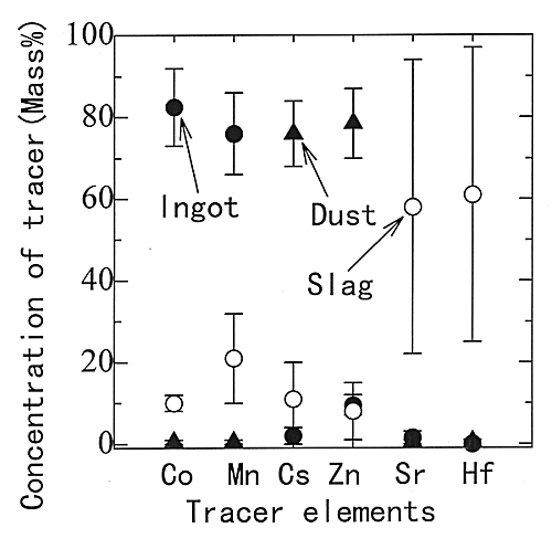
Fig. 4. Apportionment of simulated
nuclides among ingot, slang and dust.
Melting of Tube Shaped Material
4 pieces of tube shaped Alloy 600 were released from the hook with the parameter of length of released tube. Generally hook temperature increased with a decrease in the length of the released tube. However, in the length between 30 to 100mm, the temperature experienced by the hook could be confined to less than 650°K. As the approved temperature of the hook in designing is less than 900°K, there was no problem concerning the hook temperature. Even in 100mm length of tube, neither splashing out of the melt from the crucible nor tumbling of the tube, followed by rolling out from the crucible took place.
DESIGN FOR THE ENLARGEMENT OF MERC
Numerically estimated phenomena of meniscus shape, heat pattern and flow pattern as a result of the increase in high frequency energy supplied to the cold crucible of 100mm diameter are shown in Fig. 5. With an increase in input energy, height of the melt out of contact with the wall increases. Higher temperature area appears in front of the contact point of the melt with the wall in low energy input. Temperature increases with an increase in input energy. Below input energy of 63kW, electromagnetic driven flow does not take place because of the low temperature of the material which melts. However when the input energy increases up to 118kW, the material melts and electromagnetic driven flow takes place and the temperature in the melt becomes uniform. It is concluded from the calculation that the input energy of 118kW is necessary for the melting in MERC process of 100mm diameter.
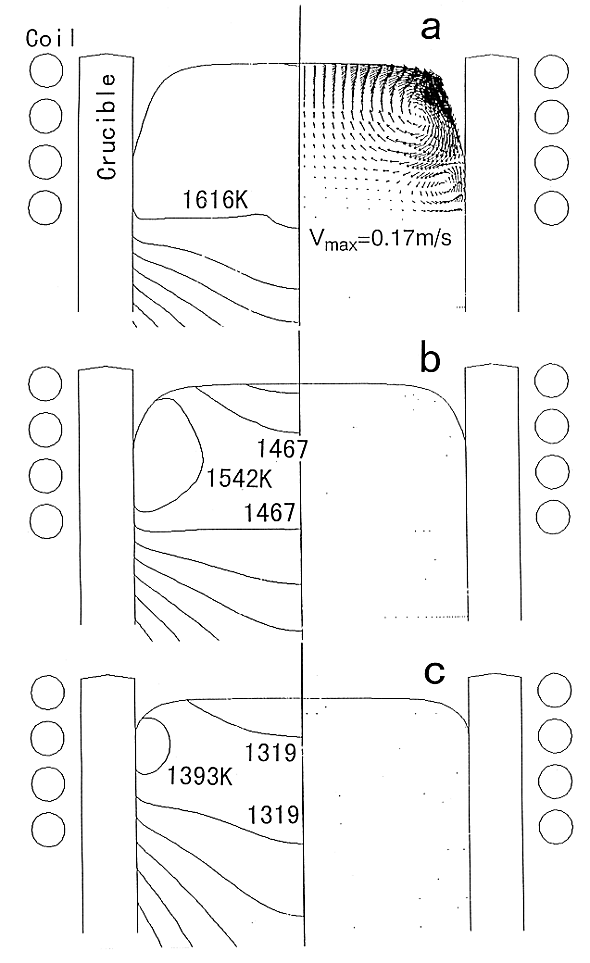
Fig. 5. Influence of high frequency
energy on heat and flow pattern (a: 118kW, b: 63kW, c: 24kW).
CONCLUSIONS
The feasibility study on MERC (Melting and Recycling of Metals by Cold Crucible) process has been recently finished in RANDEC. In MERC, an induction cold crucible, which mainly consists of a melter, decontaminator and continuous caster is used for the melting and recycling of metals contaminated at low levels with radionuclides and shaped with small cross- section, such as piping and tubing pieces, generated from the nuclear facilities. The following results were obtained.
REFERENCES