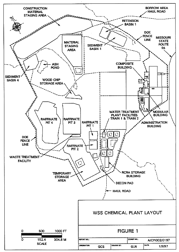
Fig. 1. Site Plan of the WSSRAP
Chemical Plant.
Glen C. Schmidt and Hugh G. Hempill
Morrison Knudsen
Corp
ABSTRACT
The Weldon Spring Site Remedial Action Project (WSSRAP) is a DOE CERCLA site located about 30 miles west of St. Louis, Missouri. This site was originally the location of the Weldon Spring Ordnance Works and was used from 1941 to 1944 for the production of conventional explosives including trinitrotoluene and dinitrotoluene. In 1957, the Atomic Energy Commission constructed a uranium feed materials plant (referred to as the chemical plant) at this site, which continued to operate until 1966. The wastes resulting from these two operations are now being remediated.
Almost 100 metric tons of miscellaneous mixed wastes in small lots have been identified at Weldon Spring. Individual parcels of waste were collected and placed in containers, sampled, analyzed and were consolidated into one of 60 waste streams. These waste streams differ from each other by type of contaminant and carrier matrix. When the identification and classification process was complete, the containers of waste material were placed in a controlled storage area to await treatment and disposal.
At the Weldon Spring site, in addition to the waste streams mentioned above, there are four raffinate pits containing sludge and wastewater that must be remediated. Originally, these raffinate pits contained 120,000 m3 of sludge and 240,000 m3 of water. Currently, the water volume in the raffinate pits has been reduced to 40,000 m3. To date, the site has treated and discharged approximately 530,000 m3 of treated water, which includes collected stormwater runoff. Remediation of the sludge is scheduled to begin in the summer of 1997.
INTRODUCTION
This paper discusses the treatment of three mixed waste streams generated at the chemical plant site:
Figure 1 is a site plan of the WSSRAP Chemical Plant.

Fig. 1. Site Plan of the WSSRAP
Chemical Plant.
Water Treatment Facility Description
The site water treatment facility consists of two process trains referred to as Train 1 and Train 2. The mission of these facilities is to treat feed water collected from various locations at the site in order to produce an effluent stream that satisfies the requirements of the WSSRAP National Pollution Discharge Elimination System (NPDES) permit for discharge to the Missouri River.
Train 1 is a 400 lpm physical/chemical treatment process train designed to treat the majority of the wastewaters found on the site. Train 2, with a capacity of 150 lpm, is capable of processing all wastewaters found on the site that contain elevated concentrations of nitrate and selenium.
Figure 2 is a block flow diagram indicating water sources and treatment.
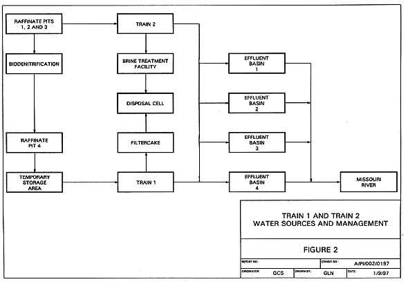
Fig. 2. Block flow diagram indicating
water sources and treatment.
Train 1 Facility Process Description
Train 1 is designed to treat Raffinate Pit 4 water and runoff collected from an outdoor mixed waste temporary storage area (TSA), which serves as a collection point for contaminated soil and rubble. Train 1 makes use of the following unit processes: a reaction tank for lime precipitation; a lamella clarifier using ferric sulfate as a coagulant; two multimedia filtration columns; two activated alumina adsorbers; two activated carbon adsorbers; five ion exchange columns (two for uranium polishing and three for nitrate polishing); a sludge thickener; a stirred batch precipitation reactor; and a filter press.
Figure 3 is the Train 1 process flow diagram.
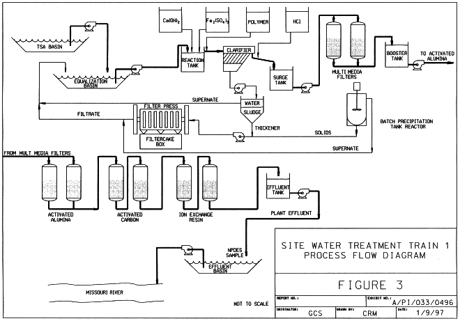
Fig. 3. Train 1 process flow diagram.
The facility has effectively treated contaminated feed water by removing uranium; thorium; radium; several heavy metals; 2,4-DNT; and fluoride to below the NPDES permit requirements. The batch precipitation tank reactor is used to remove fluoride from the activated alumina waste regeneration (AA regen) fluid as aluminum fluoride. This batch precipitation tank is also used in the treatment of small batches of contaminated wastewater collected from various locations around the site.
Train 1 Fluoride Management
The current Train 1 fluoride management facility consists of two 1.5 m diameter adsorption columns operating in parallel. Each of these vessels contains 8000 kg of 28 by 48 mesh granular activated alumina. The incoming contaminated feed water to Train 1 has a fluoride concentration of 8 mg/l, and it is treated to satisfy the NPDES discharge permit requirement of 4 mg/l. The alumina is regenerated using a 2% solution of sodium hydroxide. Each regeneration produces 20,000 liters of pH 13.5 waste liquid with high concentrations of fluoride that must be reduced. This treatment is performed in the batch precipitation tank.
The original design called for fluoride management that used lime precipitation followed by activated alumina(AA) adsorption. The AA regen fluid would then be returned directly to the head of the unit. The discharge of the waste AA regen fluid to the equalization basin dissipated the excess alkalinity. The intent of this operation was to concentrate the fluoride to an equilibrium point at which the lime precipitation unit would remove more than 50% of the fluoride entering the plant.
During the initial operating campaign, as the fluoride buildup continued in the equalization basin, it became apparent that plant production would drop to well below 50% before equilibrium conditions were established. It was obvious that, for the sake of production economics, a major portion of the fluoride was going to have to be removed from the AA regen fluid before the water could be recycled to the equalization basin. Under these conditions, the regeneration was using 1000 m3 of treated water every three days. This represented almost 58% of the plant throughput, and there were indications that the regeneration frequency was going to have to be increased. This was unacceptable for long-term operation.
Fluoride analyses of the AA regen fluid effluent were performed during the course of a regeneration cycle to determine the point at which the regeneration could be considered complete. These data were used to provide the basis for determining the volume of AA regen fluid requiring treatment. A representative sample was collected for jar testing of treatment options.
Jar tests showed good floc formation as the pH of the AA regen fluid was reduced from 13.5 to 10 by the addition of hydrochloric acid. Additional tests showed the optimum pH for fluoride removal and sludge settling to be 5.5.
Today, a typical 20,000 liter full-scale batch of AA regen fluid exhibits a pH of 13.5 and contains 12 kg of fluoride (600 mg/l), in addition to desorbed heavy metals and radionuclides. Precipitation operations are performed in a 15,000 liter stirred batch precipitation tank reactor. In addition, the system also includes equipment for making controlled additions of hydrochloric acid and lime slurry. The settled floc is dewatered in a filter press for placement in an on-site disposal cell, while the supernatant liquid is discharged to the equalization basin.
During the regeneration cycle, real time fluoride monitoring of the AA regen fluid allows the plant operators to determine when the fluoride concentration in the regen fluid is sufficiently low in order to allow it to be diverted to the equalization basin rather than collected for treatment in the batch precipitation tank.
AA regen fluid that has been collected in the batch precipitation tank is treated by first adding 20 kg of hydrated aluminum sulfate to ensure that there is adequate aluminum in the system for floc formation. Next, approximately 110 gal of concentrated hydrochloric acid are added to reduce the pH to 5.5, neutralizing the sodium hydroxide, to cause the precipitation of aluminum fluoride. The floc is allowed to settle before being pumped to a filter press. The supernatant liquid is transferred to the Train 1 equalization basin. This processing reduces the concentration of dissolved fluoride from 600 mg/l to 20 mg/l.
Table I presents typical chemical analyses of the waste regen fluid before and after treatment.
Table I Waste Activated Alumina Regeneration Fluid Chemical
Analysis

This process has been used effectively over forty times in the last two years to remove over 500 kg of fluoride. As a direct result of this process change, plant capacity has increased by more than 20% over the original design.
Wastewater Contaminated with RCRA Metals and Radionuclides
Twenty-six drums of wastewater with varying concentrations of RCRA TCLP toxic characteristic metals (RCRA metals) and radionuclides were collected during the demolition of the chemical plant buildings. The volume of these lots of waste varied from 20 liters to 200 liters with a total volume of 3,500 liters. The Train 1 batch precipitation tank was chosen as the preferred site for treating these wastewaters. The primary objective was to precipitate the RCRA metals and radionuclides to satisfy regulatory requirements. Then, the pretreated wastewater was to be combined with the water in the equalization basin for secondary treatment in Train 1.
A representative composite sample from the 26 drums was collected and used to conduct jar tests. The jar tests provided: the proper reagents to be used, the reagent dosage, mixing time, waste sludge volume, and removal efficiency. The ultimate pretreatment technique would require three different chemical reaction processes. A low pH of 2.0 was used for chromium reduction, and a relatively neutral pH of 7.5 was used for the precipitation of mercury with sodium sulfide. A high pH lime precipitation was used to remove the remaining metals and radionuclides.
After the entire waste stream of 3,500 liters was added to the batch precipitation tank, the pH was lowered to 2.0 with sulfuric acid. Sodium metabisulfite was added next at a rate of 95 mg/l to serve as the reducing agent for the hexavalent chromium present. Lime slurry was added to increase the pH to 7.5 before adding 0.5 mg/l of sodium sulfide to stabilize the mercury. Ferric sulfate was then added at a rate of 70 mg/l to serve as a coagulant for the remaining RCRA metals and radionuclides that were precipitated, using lime to raise the pH to 11.5. With the completion of the lime addition, anionic polymer was added to enhance floc formation and settling.
The supernate was analyzed for RCRA metals to document the treatment before transfer to the Train 1 equalization basin. The precipitated solids were sampled and tested for RCRA metals to demonstrate that the TCLP limits were satisfied before they were dewatered in the filter press. The filter cake was placed in temporary storage along with the site water treatment plant filter cake.
Table II lists the chemical analyses from the bench scale tests and the full-scale treatment.
Table II Metals Contaminated Water: Treated and Untreated Chemical
Analysis
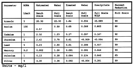
There was concern that the consolidation of the waste stream might be considered as dilution since the individual drums contained various contaminants and concentrations. The results presented in Table II for the bench scale test were used to document that the process did, in fact, precipitate the metals.
The analytical data for the full-scale treatment, when compared to that for the bench scale test establishes that a truly representative sample was collected for the bench scale test. The full-scale composited untreated waste stream was well above the RCRA toxicity level for arsenic, cadmium, and mercury. Chromium, lead, and silver were just below the RCRA limit. The treatment process achieved a reduction of greater than 90% for the six RCRA metals that were near or above the limit. The lower removal efficiencies for barium and selenium were attributed to the lower initial concentrations. The concentrations for all metals in the supernatant and the (TCLP-extracted) precipitated solids were extremely low and surpassed the pretreatment objectives.
Train 2 Process Description
Train 2 was designed to treat Raffinate Pit 3 water. The fundamental difference in treatment capability between Train 1 and Train 2 is that Train 2 removes high concentrations of nitrate and selenium.
Figure 4 is the process flow diagram for Train 2.
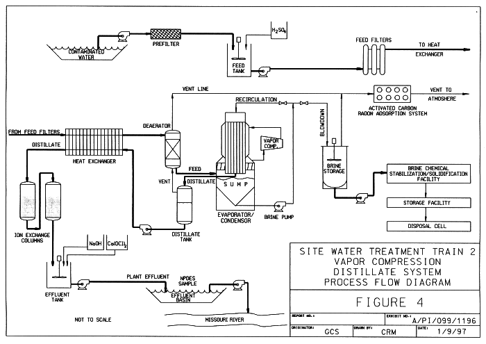
Fig. 4. Process flow diagram for
Train 2.
A submersible pump suspended from a float in Raffinate Pit 3 supplies water to Train 2. The water is pumped through a 50 micron prefilter before entering the system feed tank. The pH of the feed water is adjusted to 5.7 with 10% sulfuric acid to provide a non-scaling chemistry. The system feed pump transfers the water through a series of 25 micron filters to remove suspended material before entering a plate and frame heat exchanger.
The heat exchanger transfers heat from the hot distillate to the incoming cold feed. The cooled distillate flows to the ion exchange system, and the heated feed at 98°C is sent to the deaerator. The deaerator is a packed column that operates at a pressure slightly above atmospheric. The dissolved gases are stripped out of the heated feed water by direct contact with a portion of the 106°C steam vented from the distillate collection tank. The stripped gases exiting the top of the deaerator are combined with the remainder of the distillate tank vent stream. The combined gas streams are cooled in a series of condensers before entering the radon adsorption system. The deaerated feed is transferred directly from the bottom of the deaerator to the inlet of the evaporator/condenser sump, where it becomes part of the recirculating brine stream.
The evaporator/condenser and the associated sump vessel are the heart of the Train 2 system. A 260 kW vapor compressor adds energy to the system by compressing the vapor from the head space of the sump vessel. The compressed vapor is fed to the shell side of the evaporator/condenser where it gives up its latent heat to a concentrated brine stream circulating through tube side. The condensed vapor or distillate exits the system passing through the collection tank, the hot side of the heat exchanger, the nitrate and uranium polishing ion exchange sub-system, and finally into the effluent tank. In the effluent tank, the pH is adjusted with sodium hydroxide and a calcium hypochlorite solution is added for cyanide destruction. The treated water from the effluent tank is extremely pure, having a conductivity of 25 µS/cc.
Train 2 Waste Brine Treatment
As the feed water is distilled in the evaporator, a portion of the brine that is circulating is diverted to maintain the TDS and TSS at 22% and 6%, respectively. The temperature of the brine exiting the evaporator sump is 102°C. This side stream of brine leaving the system is collected in a 15,000 liter brine storage tank located inside the Train 2 building.
The brine production rate is directly related to the TDS level of the contaminated feed water. The design TDS level for Train 2 is 4,000 mg/l. The actual TDS was 10,000 mg/l during the campaign in the fall of 1996. The result was a dramatic increase in the brine wasting rate from the design volume estimate of 4,500 lpd to 8,000 lpd. The selenium concentration in the brine was 8 mg/l, well above the RCRA toxicity level of 1 mg/l. The brine also had elevated levels of nitrate, radium, sulfate thorium, and uranium. Table III is a typical chemical analysis of the waste brine solution.
Table III Waste Brine Solution Chemical Analysis

Waste Brine Treatment Alternatives
The Train 2 waste brine requires treatment before its eventual placement in the on-site disposal cell. The initial treatment method attempted was lime precipitation of the metals in the batch precipitation tank, followed by the filtering of the precipitate and suspended solids in the Train 1 filter press. It was intended that the supernatant liquid from the precipitation tank would be transferred to Raffinate Pit 1 or 2 for biodenitrification. This processing failed to precipitate the selenium sufficiently, and the method was abandoned.
Next, several bench scale sulfide and hydroxide precipitation techniques, both with and without coagulants, were tried. The trial coprecipitants included ferric sulfate, ferrous sulfate, ferric chloride, and aluminum sulfate. Attempts were made to reduce the selenate to more readily precipitated selenite. Over 50 separate precipitation trials were made using a variety of reagents, dosages, and pH levels. Some approached the goal of 1 mg/l of selenium but none achieved it.
The removal of selenium concentrations was also attempted using adsorption techniques. Several varieties of activated alumina and activated carbon were tested in a wide variety of loadings and pH levels. The activated alumina did manage to reduce the selenium concentration to less than 1 mg/l, but the quantity of alumina required made the process infeasible. Sulfate is reported to compete with selenium in adsorption processes, and likely was the reason for the lack of success. Over 70 adsorption tests were conducted.
Ion exchange and reverse osmosis were also considered. Speciation analyses showed that the WSSRAP waste brine selenate to selenite ratio to be 9 to 1. While selenate is reported to be removed by ion exchange, it was rejected because competition from sulfate was again expected to hamper removal. Reverse osmosis was considered impractical due to the high level of total solids (28%) in the brine.
In the final analysis, chemical stabilization and solidification (CSS) was considered to be the most viable option for waste brine treatment, and steps were taken to develop a satisfactory technique.
Waste Brine Chemical Stabilization and Solidification
Bench scale tests indicated that a Portland cement/lime binder could be used with the waste brine to produce a monolithic mass with an unconfined compressive strength (UCS) well in excess of 340 kPa. This binder would also chemically stabilize the contained RCRA metals. The tests were conducted using various ratios of Portland cement to lime to waste brine. The final formulation used 1.2 kg of a 1-to-1-weight-ratio of a Portland cement and lime binder to treat 1 liter of waste brine.
Full-scale waste brine treatment operations begin by transferring the waste brine slurry from the 15,000 liter waste brine storage tank in the Train 2 building to two 125,000 liter glass-lined brine storage tanks that provide additional cooling time and surge capacity. The brine is held in these tanks prior to treatment at the CSS plant. A batch volume of 700 liters of brine is first added to the pug mill where it is mixed with 850 kg of binder mix. This mix produces 1 m3 of product with a density of 1.6 kg/l. The bulking factor for this CSS process is 1.4 (i.e., 1 m3 of waste brine slurry produces 1.4 m3 of CSS brine product). The final UCS is greater than 210,00 kPa.
The CSS brine product is formed into 1 m3 blocks in forms lined with polypropylene bulk bags. The bulk bags include 4 lifting straps for moving the CSS product. The blocks will be placed in the on-site disposal cell. To date, 530 m3 of brine have been successfully treated using this process.
CONCLUSIONS
Fluoride management by lime precipitation followed by activated alumina adsorption is ineffective when the AA regen fluid is recycled to the head of the system without intervening treatment. However, when the regeneration fluid loop is arranged to include a batch precipitation system, fluorides can be managed efficiently and effectively.
Miscellaneous wastewaters containing all eight RCRA metals can be effectively treated in a single tank batch precipitation process. By using several chemical reactions in the proper sequence, all eight RCRA metals were effectively removed. The sludge by-product satisfactorily passes the TCLP test for toxic metals.
As part of any system design effort, careful consideration must be given to the management of secondary wastes produced by a treatment system. It is unreasonable to assume that a search of the literature will produce satisfactory management techniques for treating secondary waste steams. The actual waste material must be tested in the laboratory to prove its efficacy. This was illustrated in the search by WSSRAP personnel for a solution to the waste brine stabilization problem.
Waste brine high in nitrates and sulfates can be stabilized with a cement/lime binding agent. This process also effectively stabilized selenium to below detection limits on the TCLP extract.