Terry J. Wickland
Nuclear Filter Technology, Inc.
Marty Mataya
Safe Sites of Colorado
Rocky Flats
Plant
ABSTRACT
The hydrogen diffusion rate through three different types of tape seal on a 2 quart Vollrath® slip lid dressing container have been measured. The three different types of tape --either yellow Slipknot® #44 Vinyl, Slipknot white polyethylene, or 3M brand # 850 aluminized polyester tape, are presently used throughout the DOE complex for securing the lid to the body of the Vollrath 88020 slip lid dressing container. In addition to measuring the diffusion of hydrogen through a single layer of tape, the effect of a second layer of tape on hydrogen diffusivity has been measured. The measurements are the first of their kind and are required to assure that potentially explosive concentrations of hydrogen gas do not accumulate within the containers that are used to store plutonium residues.
BACKGROUND
Plutonium metals, oxides and salts are stored in stainless steel, slip-lid Vollrath 88020 two-quart dressing containers. Generally, the lid is sealed to the container body using either 2" wide yellow Vinyl Slipknot #44 adhesive tape, 2" wide Slipknot white polyethylene tape, or 1" wide 3M brand #850 aluminized polyester tape. An ideal seal configuration will be one that provides an excellent seal, allows rapid diffusion of hydrogen, yet allows nearly zero water vapor back diffusion.
There has been little research done towards accurate measurements of
diffusion through seals of plutonium bearing storage containers. At the Los
Alamos National Laboratory, it has been shown that in some cases hydrogen gas
will not diffuse through heat sealed, or 'horse-tail' tied, polyethylene waste
bags at a rate sufficient to assure that explosive hydrogen gas concentrations
are not exceeded(1). The LANL study reports a diffusion rate of 2.8E-7
moles/second/mole fraction (m/s/![]() m)
through a heat sealed polyethylene bag. A hydrogen diffusion rate of 3.6 E-7
m/s/
m)
through a heat sealed polyethylene bag. A hydrogen diffusion rate of 3.6 E-7
m/s/![]() m
is reported through the same type of bag closed with a 'horse-tail' seal. An
acceptance criterion established in WIPP TRUPACT II Codes is that a safe
hydrogen diffusion rate will be one that is greater than 1.9 E-6 m/s/
m
is reported through the same type of bag closed with a 'horse-tail' seal. An
acceptance criterion established in WIPP TRUPACT II Codes is that a safe
hydrogen diffusion rate will be one that is greater than 1.9 E-6 m/s/![]() m.
m.
At the Rocky Flats Environmental Site, it has been shown that under laboratory conditions water vapors condense and accumulate as liquid in the containers at a rate of about 0.76 moles per year. The increase in water content within the container can cause greater hydrogen gas generation, accelerate corrosion, and can also become a criticality infraction risk.
The container and tape seal configurations described in this report are not intended to meet requirements of WIPP TRUPACT II. Reference is made for example only. The intent of the study was to measure the hydrogen diffusivity values for each tape configuration. The rate of diffusion must be measured so that hydrogen gas generation and diffusion models will provide accurate estimates of risk associated with containers sealed in this manner.
TEST METHOD
The hydrogen diffusivity test is described in Nuclear Filter Technology procedure P.S. 26.0 which is used as a quality assurance measure to verify that hydrogen diffusivity criteria are met for drum venting filters.
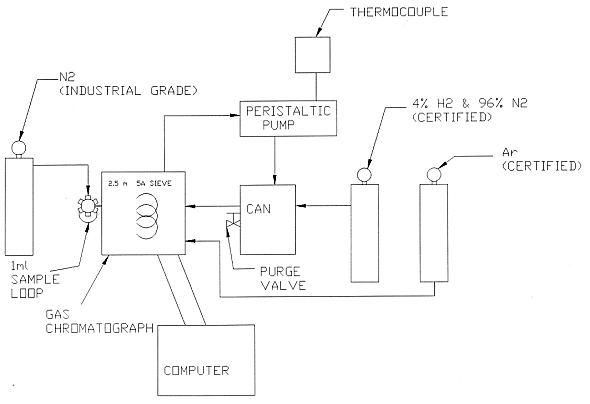
Figure 1 shows a schematic representation of the test assembly. The test method utilizes a gas chromatograph (GC) with a thermal conductivity detector and a 3 meter, 0.5 micron column. Use of Argon as a carrier gas allows detection of hydrogen, nitrogen and oxygen. A certified mixture of 4.0% hydrogen gas with a balance of nitrogen is purged through the test vessel and connective tubing. Vessel temperature, and atmospheric pressure are monitored during the test.
There were two phases of hydrogen diffusion testing. The first phase provided an adequate rough order of magnitude estimate of hydrogen permeability through the three types of tape. In the second phase, refinements to the test apparatus and methods will provide very accurate comparisons of hydrogen permeability through the three tape seals. Both phases of study are described here.
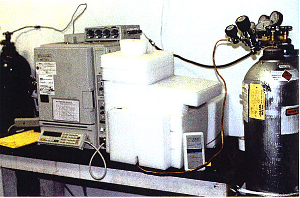
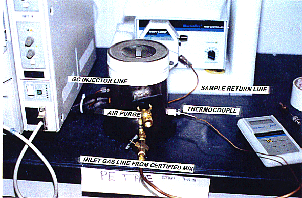
A peristaltic pump circulates the test mixture through the gas chromatograph and returns test mixture to the test vessel. At the start of a test and at five minute intervals, a sample of the gas is injected into the detector for analysis. Seven one-milliliter samples are taken over a 35 minute period. Figure 2 shows the diffusion test equipment, with the 2" thick insulation around the test canister. The insulation surrounding the test container is to moderate temperature cycling. Temperature cycling causes a 'pumping' action on the gas within the container that would otherwise cause hydrogen gas losses not related to diffusion. Figure 3 shows the polyethylene taped canister, the air purge valve, thermocouple connection, inlet purge line and the GC injection line. Not shown is the gas sample return line.
The amount of hydrogen in the test vessel decays over time due to diffusion through the taped seal and through tubing and connections. The amount of hydrogen in the container is related to the chromatogram peak area. The decay rate, or hydrogen diffusivity , D, through the assembly is given by:
D = PV/t RT Ln(Ho/Ht)
Where P is atmospheric pressure, V is the volume of the vessel with
connective tubing, t is elapsed time in seconds, R is the Ideal Gas Constant,
and T is the temperature in Kelvin. The diffusion rate, D, is in moles/ second /
mole fraction (m/s/![]() m).
The initial concentration of hydrogen given by the chromatogram peak area is Ho,
and the amount of hydrogen after time t is Ht.
m).
The initial concentration of hydrogen given by the chromatogram peak area is Ho,
and the amount of hydrogen after time t is Ht.
PHASE-I TEST METHOD
During each diffusion test, which lasts up to 5 days, the barometric pressure and temperature are monitored. Barometric pressure is determined by calling the Jefferson County Airport where barometric pressure is reported. Temperature is monitored by the thermocouple inside the test container, and recorded several times each day. Both the pressure P, and temperature T, components in the hydrogen diffusivity calculations are arithmetically averaged using the highest and lowest barometric pressure, and highest and lowest temperature values recorded during the test period. Losses due to 'pumping' of the gas, a result of changing atmospheric conditions, are not taken into account. The Los Alamos report suggests that atmospheric changes are partly responsible for errors in diffusion measurements.

Fig. 1. Schematic diagram of Hydrogen
Diffusion Test System.

Fig. 2. Shows the Hydrogen Diffusion
Test Apparatus With Insulation

Fig. 3. Shows the Polyethylene Taped
Can
TEST MATRIX
Two Vollrath two quart 88020 stainless steel containers were equipped with fittings to accommodate the required valves and line connections. One container was used for the taped seal tests, and the second had the lid tungsten-inert-gas (TIG) welded to the body. The fully TIG welded configuration provides the baseline from which system hydrogen diffusion losses can be calculated.
Two stainless steel fittings are TIG welded to the container to allow attachment of the peristaltic pump inlet and outlet ports. One additional fitting was attached to allow temperature monitoring. Only one test vessel is required for tests since each different tape is easily removed for the subsequent test.
Five data acquisition sequences were conducted for each container configuration, where each sequence injected 7 one milliliter gas samples. Therefore, for a given test run, 35 data points were obtained.
There were six tape seal configurations tested. The first was the slip lid with no seal tape; this provides the fastest hydrogen diffusion rate and the upper boundary condition. The second configuration tested is the Vollrath 88020 canister with a fully TIG welded seal. The TIG welded seal provides the slowest diffusion rates, is the lower boundary condition and is assumed to represent the system diffusivity. The TIG welded canister configuration was duplicated in order to demonstrate system repeatability.
The third configuration is a Vollrath 88020 canister sealed with yellow vinyl tape. The fourth configuration is a canister sealed with white polyethylene tape, and the fifth configuration is the canister sealed with aluminized polyester tape. The final configuration is a double layer of yellow Vinyl tape.
PHASE -II TEST METHOD
The second phase, at the time of publication, is still underway. The second
phase duplicated the above tests after making several improvements in order to
obtain more reliable data. It was thought that better information could be
obtained by minimizing system losses. In the second phase, system hydrogen
losses, measured using the TIG welded can, were reduce by about two orders of
magnitude, to about 2 E-10 m/s/![]() m.
This was accomplished by eliminating Teflon tape in all the fittings and sealing
each with multiple layers of two part epoxy. When possible, fittings were TIG
welded directly to the can. Barbed fittings were replaced with Swagelok®
fittings. The pressure gage and thermocouple were eliminated from the test
canisters which further reduced potential leak paths. Finally, the test
apparatus was configured such that three meters of unnecessary tubing were
eliminated.
m.
This was accomplished by eliminating Teflon tape in all the fittings and sealing
each with multiple layers of two part epoxy. When possible, fittings were TIG
welded directly to the can. Barbed fittings were replaced with Swagelok®
fittings. The pressure gage and thermocouple were eliminated from the test
canisters which further reduced potential leak paths. Finally, the test
apparatus was configured such that three meters of unnecessary tubing were
eliminated.
The hydrogen diffusion rates through tygon and Viton were measured, as well as when the tubes were wrapped with the aluminized polyester tape.
The results are given below:
| H2 DIFFUSION RATE | |
| PERISTALTIC PUMP TUBE | Mole/Inch S/Mole Fraction (m/s/ |
| Viton Tube Wrapped in Metalized Tape | 1.20 E-11 |
| Viton Tube - No tape | 1.36 E-11 |
| Tygon Tube Wrapped in Metalized Tape | 2.60 E-11 |
| Tygon Tube - No tape | 3.80 E-11 |
Viton tube, wrapped in aluminized polyester tape, was selected for use because its hydrogen permeability is the lowest. In the actual test of the can, about 6 inches of the tubing are required. The aluminized tape wrapped on the Viton tube does not interfere with the pumping action of the peristaltic pump.
Perhaps the most significant improvement in testing was that only one sample of gas was injected at each period, rather than 5. Although the container has a volume of slightly more than 2 liters, it was found that taking 5 one milliliter samples at each time interval, totaling 35 milliliters, represented a fairly significant loss of hydrogen.
SUMMARY RESULTS -- PHASE -1
The hydrogen diffusivity results for Phase -1 of each canister configuration is summarized in Table I. Due to the unexplainable large variation in the first data acquisition sequence, it is not included in averaging calculations. It is believed that averaging the final four data acquisition sets for each test run is the best estimate of actual hydrogen diffusion.
Table I Phase -1 Hydrogen Diffusivity Through Various Tape Seals

DISCUSSION OF PHASE -1 TEST RESULTS
The values shown represent the actual calculated diffusion rates; system losses through fittings and tubing are not subtracted. The TIG welded canister configuration represents hydrogen losses through the 'system'. Table I shows the total diffusion, diffusion through the tape plus the diffusion through the system. By minimizing the system losses, the true hydrogen diffusion rate through the tape becomes more significant. System losses of at least one order of magnitude lower than the measured rate of diffusion would allow more reliance on the measured diffusion rate through the tape itself. Thus, by minimizing the system hydrogen losses, a truer value is determined for the diffusion rate through the tape itself.
The hydrogen diffusion rate through the TIG welded can was measured two
times, once at 0.338 and once at 0.231 E-7 m/s/![]() m.
The second phase of testing significantly reduced the hydrogen losses through
the TIG welded can. One challenge with measuring the system losses is that the
diffusion process is extremely slow and even the slightest uncontrolled leak
causes skewed data.
m.
The second phase of testing significantly reduced the hydrogen losses through
the TIG welded can. One challenge with measuring the system losses is that the
diffusion process is extremely slow and even the slightest uncontrolled leak
causes skewed data.
The hydrogen diffusion rate through the aluminized polyester tape is 0.329
E-07 m/s/![]() m.
The diffusion rate through the polyethylene tape is 0.417 E-07 m/s/
m.
The diffusion rate through the polyethylene tape is 0.417 E-07 m/s/![]() m.
In both cases, the measured values are close to that measured through the TIG
welded can. The concern, therefore, is that leakage through the system may be
masking the true diffusion through the various tapes.
m.
In both cases, the measured values are close to that measured through the TIG
welded can. The concern, therefore, is that leakage through the system may be
masking the true diffusion through the various tapes.
The hydrogen diffusivity for the yellow taped canister is 1.5 E-07 m/s/m. The diffusion rate measured through the yellow tape is the most reliable value obtained from this study since it is at least 5 times greater than that observed through the TIG welded can.
The addition of a second layer of yellow tape reduced the diffusion rate
down by a factor of 4.5, rather than the expected 2, to 0.324 E-7 m/s/![]() m.
Diffusion theory predicted that the second layer of yellow tape would lower the
diffusion rate by a factor of 2. It is not known why this discrepancy with
theory exists.
m.
Diffusion theory predicted that the second layer of yellow tape would lower the
diffusion rate by a factor of 2. It is not known why this discrepancy with
theory exists.
The statistical test of two independent means method is used to compare mean diffusion rates for each configuration to determine if statistically significant differences exist between configurations. A Z score is calculated. The Z score is a statistical measure of the difference between two mean diffusion rates. If the Z score is greater than 1.96, then at the 95% confidence level, there is a statistically significant difference between the two average diffusion rates.
Table II Z Scores For Difference Between Two Independent Means

The Z score of 6.6 calculated for the hydrogen diffusion rates measured for the first and second test run of TIG welded seal indicates a statistically significant difference. There should not be a significant difference between the two test runs because they were set up the same. The reason, at this time, is unexplainable. The test system was be improved in phase -2 tests by eliminating Teflon tape and welding the joints.
PHASE -2 TEST RESULTS
Phase -2 hydrogen diffusivity tests are, at the time of publication, still in process. The Vollrath 88020 sealed with a TIG welded seam, yellow Vinyl tape and polyethylene tape have been measured. The aluminized polyester tape is scheduled to be tested by March 1997. Each type of tape will be tested a second and third time in order to make statistical comparisons. The authors anticipate completion of testing by March 1997 with a final report issued by late April 1997. Table III below summarizes the test results.
Table III Phase -2 Hydrogen Diffusivity Through Various Tape Seals

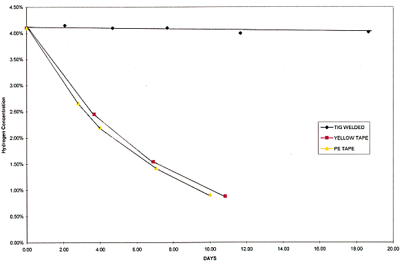
The TIG welded can was tested for 18 days. The hydrogen diffusion rate was
measured at 2 E-10 m/s/![]() m.
The hydrogen loss through the TIG welded can, in this second phase of testing,
is about two orders of magnitude lower than was measured during the first phase
of testing (2.5 E-8 m/s/
m.
The hydrogen loss through the TIG welded can, in this second phase of testing,
is about two orders of magnitude lower than was measured during the first phase
of testing (2.5 E-8 m/s/![]() m).
m).
The hydrogen diffusion rate through the yellow vinyl tape was measured at
1.12 E-7 m/s/![]() m
over a period of 11 days. During the first phase of testing, diffusion through
yellow tape was measured at 1.5 E-7 m/s/
m
over a period of 11 days. During the first phase of testing, diffusion through
yellow tape was measured at 1.5 E-7 m/s/![]() m.
At this time, not enough date is available to determine if a statistically
significant difference exists.
m.
At this time, not enough date is available to determine if a statistically
significant difference exists.
The hydrogen diffusion rate through the polyethylene tape was measured at 1.21 E-7 m/s/m over a period of 10 days. During the first phase of testing, diffusion through polyethylene tape was measured at 0.41 E-7 m/s/m. This more rapid diffusion rate may be the result of wrinkles in the tape closure. Measuring the rate a second and third time will show if the slight wrinkles contributed to the higher rate.

Fig. 4. Demonstrates the hydrogen
concentration loss over time for the TIG welded can, yellow tape, and
polyethylene tape.
CONCLUSION
All DOE sites store solid plutonium residues including metals, salts and powders in some form of a steel container. The practice has been to secure the slip lid top of the container to the body using one of several types of tape. The water accumulation rate inside the containers, from water vapor diffusing into the containers has been well established at the Rocky Flats Plant. This study provides the first reasonable measured values of hydrogen diffusion out the container. Ideally, it is desirable to allow hydrogen to leave the can freely, yet not allow any water vapor into the can.
The results of this study indicate that the hydrogen diffusion rate through
the Vollrath 88020 can sealed with yellow vinyl tape is on the order 1.2 E-7
m/s/![]() m.
The hydrogen diffusion rate through the Vollrath 88020 can sealed with
polyethylene tape is on the order of 0.9 E-7 m/s
m.
The hydrogen diffusion rate through the Vollrath 88020 can sealed with
polyethylene tape is on the order of 0.9 E-7 m/s![]() /m.
The diffusion rate through the Vollrath 88020 can sealed with 3M aluminized
polyester tape is on the order of 0.5 E-7 m/s/
/m.
The diffusion rate through the Vollrath 88020 can sealed with 3M aluminized
polyester tape is on the order of 0.5 E-7 m/s/![]() m.
m.
Personnel from Rocky Flats plant verified test procedures, contributed to the experimental design and edited this report. This study was funded under Rocky Flats Plant Safe-Sites of Colorado order # SSC-000068LD and SS 703384BS.
NOTES