Table I Properties and Shielding Effectiveness for Several Materials
Used or Proposed for SNF Casks
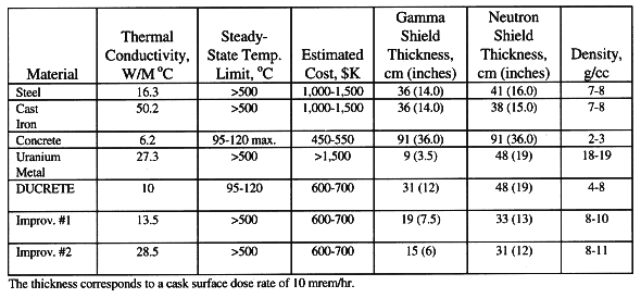
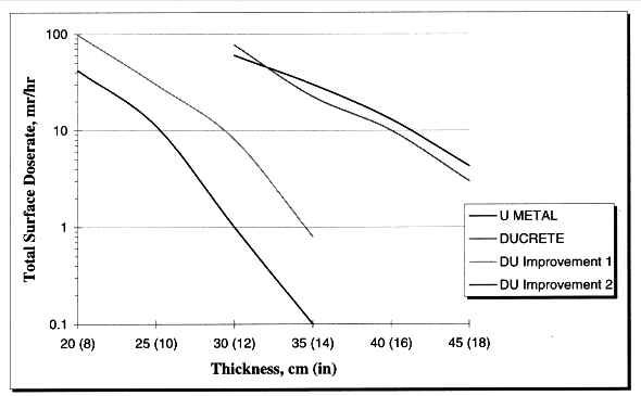
Fig. 1. Total radiation dose from SNF
with various thicknesses of shielding materials
Steven M. Mirsky, Alexander P. Murray, and Stephen J. Krill,
Jr.
Science Applications International Corporation (SAIC)
20201
Century Boulevard
Germantown, Maryland 20874
Phone Number: (301)
353-1889 Fax Number: (301) 428-0145
ABSTRACT
Adequate shielding of highly radioactive materials remains a concern for both the nuclear industry and the public, particularly for spent nuclear fuel (SNF) and high-level waste (HLW). Current shielding relies upon heterogeneous combinations of metal and hydrogenous materials or mammoth concrete structures. This paper discusses new shielding materials and concepts based upon dense uranium dioxide that provide optimal neutron and gamma shielding for SNF and HLW applications. The materials include "DUCRETE" - a combination of uranium dioxide and concrete - and other improved materials. The new materials possess superior heat transfer and shielding characteristics in a single material, without the processing difficulties of uranium metal. One shield material is composed of waste products from the nuclear and petrochemical industries which, when combined and treated, becomes suitable for direct emplacement in a future geologic repository. These new shield materials are ideal for use in SNF and HLW storage, transport, and disposal casks resulting in smaller, lighter, and less expensive casks than comparable current designs. Using the standard regulatory analysis approach, a typical 24 PWR SNF assembly storage cask would use a shield wall which could be as much as 50%-70% thinner than current concrete cask designs and would eliminate the need for internal heat removal air passages. Typical, loaded cask weights are in the 80-90 tonne range and reduce operator exposure as compared to existing designs. Key shielding, thermal, and chemical properties are presented to demonstrate the capabilities, including its suitability for direct disposal of the dense uranium dioxide material. Cost estimates are also provided for typical cask designs, and indicate competitive life cycle costs are achievable. The paper concludes that this nonmetallic, dense uranium dioxide shielding allows the advantages of metal casks to be achieved with lower life cycle costs than either metal or concrete casks, in an environmentally compatible package.
INTRODUCTION
Over 80,000 tons of SNF will have been generated by the current U.S. commercial nuclear power industry over the next 20 years (1, 2). This SNF, along with a wide range of HLW, will need to be safely stored and eventually transported and placed into a national waste repository. Existing shielding designs rely heavily upon concrete. Concrete possesses moderate shielding properties. However, its relatively low cost and easy workability allow thick-walled designs.
Typical thicknesses often exceed 90 cm (3 ft). However, concrete has a number of limitations:
This paper proposes, analyzes, and discusses new shielding concepts and cask designs based upon dense uranium dioxide that satisfy these national needs.
MARKET ASSESSMENT
Depleted uranium (DU) has been proposed as radiation shielding many times - indeed, this was one of its principal uses (in x-ray machines) prior to the nuclear age. However, DU has only found limited use because of its availability, liability, and cost; all of these are intertwined and related to the use of DU in a metallic form, requiring machining in a special plant. Fortunately, there are significant sources of DU available from enrichment operations (the so-called "tails"), potentially approaching a million tonnes as the hexafluoride worldwide. Several processes also exist for converting the hexafluoride into a dense dioxide on a large scale. Thus, a more than adequate supply of feed material is available. Liability accrues primarily from the disposal of DU. Use of DU in the SNF repository addresses a shielding need and the DU disposal liability. Suitably large plants can obtain the necessary economies of scale.
The commercial reactors in the U.S. have generated around 30,000 tonnes of SNF. The projected, cumulative total over the next two decades is expected to exceed 80,000 tonnes. For space and cost reasons, several utilities have moved SNF from wet storage pools into dry storage containers and casks, and several dry storage cask designs have been licensed and are in use. Concrete shielded designs account for most of the SNF in dry storage. Delays in SNF disposal will continue the movement of SNF into dry storage. Potentially, 10,000 to 12,000 storage containers based upon existing designs could be needed at utility sites, government locations, or a combination of the two. A multi-purpose canister (MPC) has also been proposed for storage, transportation, and disposal of SNF (2). Various MPC designs exist, some directly incorporating shielding, and some using shielding overpacks. Shielding and size criteria result in MPC's holding less SNF than current designs, and, potentially, another 12,000 to 15,000 containers could be required.
The U.S. Department of Energy (DOE) also has SNF materials which are less than 5% of the commercial fuel mass, but, in terms of volume, are equivalent to 10% or more of the commercial SNF due to thermal and criticality constraints (3). DOE also plans to generate 15,000 to 20,000 cylinders of vitrified HLW. Thus, DOE has requirements for at least 5,000 heavily shielded containers for this vitrified HLW.
Therefore, there exists a market for at least 15,000 containers with significant shielding requirements. Using 40 tonnes of uranium per container as a first approximation (4, 5), then the demand would total some 600,000 tonnes (as U). The higher estimate indicates a potential for 27,000 containers, corresponding to over a million tonnes of uranium. Thus, U.S. shielding requirements could easily consume the entire DU inventory.
SHIELDING TECHNOLOGY AND POTENTIAL DESIGNS
Effective shielding of SNF mandates the use of materials capable of attenuating both gamma and neutron radiation; in many cases, neutron radiation accounts for the majority of the dose with most SNF source terms. These require materials with contradictory properties: effective gamma shielding requires a dense, high atomic weight material, while effective neutron shielding needs a low atomic weight material. Commercial designs overcome this dilemma by either using discrete, heterogeneous gamma and neutron shields (e.g., steel and polyethylene), or by using large thicknesses of relatively low density materials as homogeneous shields. Table I presents properties of several shielding materials and their effectiveness with a standard, 24 PWR assembly source term (40,000 MWd/te, 4% uranium-235 initial enrichment, 5-year cooled). Note that the thickness required for neutron radiation shielding dominates. Clearly, uranium metal is extremely effective for gamma shielding, but very poor at neutron shielding. However, as a heterogeneous shield material (say, with 7.5-10 cm [3-4 inches] of polyethylene), the uranium metal thickness becomes comparable to that with DUCRETE. Note that DUCRETE has improved properties and reduced thicknesses as compared to normal concrete, but still suffers many of the same limitations as ordinary concrete. Improvements can be made to enhance the shielding performance and obtain significantly improved thermal properties, as shown by the two improved DU forms in Table I. Figure 1 provides a graphical representation of the total dose rate (gamma and neutron) for several materials, as a function of thickness.
Table I Properties and Shielding Effectiveness for Several Materials
Used or Proposed for SNF Casks


Fig. 1. Total radiation dose from SNF
with various thicknesses of shielding materials
Dry storage of SNF utilizes both horizontal and vertical cask designs. Regulators will probably require encasement of the DU compound within steel shells, which is likely to be easier with a vertical design. Figure 2 illustrates one such vertical design. The use of DUCRETE reduces the wall thickness from around 90 cm (regular concrete) to approximately 30 cm (12 inches). The improved DU form reduces this to around 20 cm (8 inches). The vertical cask consumes approximately 45 tonnes of depleted uranium dioxide as shielding. Structural steel members account for an additional 15-20 tonnes. Estimates place the SNF loaded cask weight in the 80-90 tonne range. This is well within the crane lift limits at many facilities and 20-30 tonnes below other shielded cask weights.
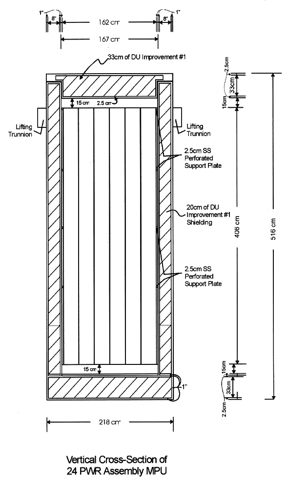
Fig. 2. Typical vertical cask for SNF
storage with DUCRETE shielding
SHIELDING MANUFACTURING PROCESS
The manufacture of DUCRETE shielding constitutes a relatively simple, low temperature process. The current practice for storage casks uses a centralized facility for manufacturing the basket and inner canister that contain the fuel, but local contractors at a utility site for the concrete cask work itself. In contrast, the use of uranium requires a centralized manufacturing facility. Figure 3 displays the overall mass and energy balances. At a rate of 500 canisters annually, the plant consumes some 22,500 te of depleted uranium dioxide annually. The plant receives the DU material as either dense pellets or microspheres. A high shear mixer combines the DU with cement, and this is sequentially cast into the annular shell of a partially assembled cask. After curing, sealing, inspections, and temporary storage, the process ships the cask to a utility or government site for use. Most of the energy requirements accrue from facility and not process loads. An integrated design that combines DU conversion to the dense dioxide has also been analyzed. This offers synergistic advantages, such as shared facilities and minimal transportation.
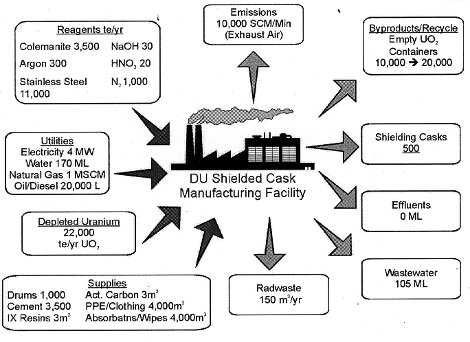
Fig. 3. Overall Mass and Energy
Balances for DUO2 Shielding Cask Manufacture
FACILITY DESIGN
A design for a stand alone facility has been generated. The facility consists of three types of buildings:
The design is roughly comparable to a small manufacturing plant. It incorporates automated high shear mixers, numerous cranes, and metal working equipment. The facility handles and produces DUCRETE and the improved DU forms with low temperature processing and minimal energy for dispersion, and, hence, special construction is not necessary for hazard mitigation. Site requirements are minimal (8-12 hectares), with no required distances to the public. Figure 3 provides the overall mass and energy balances.
An integrated facility design that includes DU conversion into the dense dioxide has also been created. This offers significant economies of scale. However, it requires a considerably larger site (upwards of 300 hectares or more) because of mitigating potential releases of fluorides from conversion operation accidents.
DU is a radioactive material, and the processing of DUCRETE and improved DU forms generates radioactive wastes. NRC regulations categorize the casks and the wastes as low-level (6). However, the NRC currently categorizes the disposal of large quantities of DU as "special" low-level waste, requiring mined cavities or other below surface disposal methods. Hence, the DU shielding must be compatible with the SNF disposal repository. The temperature and heat transfer properties of concrete, DUCRETE, and related forms restrict their use as SNF shielding to repository heat loadings of around 40 KW/hectare or less. Current repository plans call for much higher thermal loadings in the repository (140 KW/hectare or more) with long term, cask surface temperatures exceeding 200°C (7). Only metals and the improved DU forms can meet these requirements. Estimates place the DU cask, manufacturing low-level waste generation at 0.3 m3/cask. Conversion operations add 0.5 m3/cask, for a total under 1 m3/cask. This compares favorably with a cask internal volume of approximately 9 m3.
PROCESS SCALING AND ECONOMICS
Analyses have been conducted for plants manufacturing between 125 and 750 DU casks per year. Figure 4 presents the results. Finished cask cost depends strongly upon throughput; below a capacity of about 250 casks per year, the unit cost exceeds $800,000 for a 24 PWR assembly design. Capacities of 400-600 casks annually correspond to unit costs of $500,000 to $600,000. DU charges contribute 30-40% of the total cost. For comparison, current metal storage cask designs typically cost $1,000,000 to $1,500,000 and concrete casks cost $400,000 to $600,000 each. As shown in Fig. 4, current metal and concrete cask designs are more modular and do not benefit greatly from economies of scale when compared to the DU cask. Consequently, the DU casks provide the thermal and size advantages of metal casks at initial capital investments comparable to concrete casks. Furthermore, colocation with the conversion facility and optimization potentially offers a 10-20% reduction in unit cask costs.
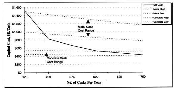
Fig. 4. Approximate Cost versus Cask
Manufacturing Capacity
Life-cycle cost analyses (LCCA) are ongoing, and depend greatly on future events in the Federal Repository and SNF programs. While MPC's are being discussed and dual-purpose casks are undergoing license reviews, all currently loaded storage casks will have to be unloaded and placed into transportation and/or disposal canisters sometime in the future. The smaller dimensions and better radiation attenuation of DUCRETE and related DU shielding materials make them very attractive, either as MPC's or shielding overpacks. DU shielding also has beneficial properties for an SNF disposal site. Some of these factors are difficult to quantify but preliminary analyses imply significant life cycle cost savings with DU forms provided cask standardization, team integration, and large capacities are used.
SUMMARY AND CONCLUSIONS
This paper analyzes new and improved shielding based upon nonmetallic forms of depleted uranium, such as a mixture of depleted uranium dioxide in concrete (DUCRETE) and DU analogues. The evaluation of radiation attenuation and other properties indicates significant advantages are possible, including reduced sizes and weights as compared to conventional shielding materials. Processing methods and a design have been identified and evaluated. A facility design has been generated. Cost analyses imply competitiveness at annual capacities above 250 SNF casks. Nonmetallic DU shielding offers significant advantages provided standardization, team integration, and large capacities are used.
REFERENCES