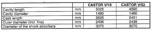
Table I Main Geometry of the CASTOR V Cask.
Dr. R. Diersch, Dr. G. Dreier, H. Stelzer
GNB mbH
Gesellschaft für Nuklear-Behälter mbH
Hollestraße 7a
D-45127 Essen, Germany
Phone: (1149) 201 - 109 - 1722
ABSTRACT
GNB Gesellschaft für Nuklear Behälter mbH has a long term experience in developing casks for the transport and storage of spent fuel assemblies. A main type of casks built by GNB is the CASTOR type made of ductile cast iron GGG 40. All design criteria including all tests according to the IAEA regulations as a type B(U) F package (IAEA) and the acceptance criteria for the German storage sites are fulfilled by the CASTOR V casks family which has been shown by calculational analysis and by analogue evaluations on the base of experiments.
The most modern high capacity casks of the CASTOR V type family have been developed for transport and long term interim storage of 19 PWR and 52 BWR spent fuel assemblies. The new casks of the CASTOR V type family are, according to the decay time of approx. 5 years and the number of fuel assemblies to be put in the cask, called CASTOR V/19 and CASTOR V/52. The development of another cask basing on the same design will be finished in 1997. This cask will be able to transport and to store 21 short PWR spent fuel assemblies.
The initial enrichment of the fuel elements to be transported and stored in the CASTOR V casks may be up to 4.6 wt-% U235 and the burn up values may increase up to 65 GWd/MgHM. MOX fuel assemblies may also be transported and stored in CASTOR V casks.
Because of the similar cask bodies of the CASTOR V family it was possible to minimize the time for the acceptance of the casks during the licensing procedures. The mechanical and thermal layout of the CASTOR V family are the main foci of this report.
GENERAL DESCRIPTION
The cask body consists of a thick walled, cylindrical cask body made in one piece of ductile cast iron (DCI). DCI exhibits sufficient ductility and resistance to corrosion. The inner surfaces of the cask are nickel coated, the outer surfaces have an easily decontaminating paint on the basis of epoxy resin. For a better passive heat removal off the casks there are machined radial fins with a height of 60 mm on the cylindrical outer surface of the cask.
The primary and the secondary lid are made of stainless steel and have separate metallic and elastomer seals to secure leak tightness. Both lids are fitted by screws.
For handling operations four trunnions, two each are placed at the top and bottom ends of the cask. The trunnions are designed according to the German KTA regulation 3905.
For a better neutron shielding there are moderator rods within the cask wall and moderator plates on the bottom and lid side of the cask. The material of the moderator is polyethylene.
In the cask cavity, a fuel basket made of partly boronated stainless steel is located. The basket provides fuel assembly support, criticality control and heat conduction paths. The cask body together with the lids and seals is used as the confinement system.
During transport on the wagon wooden shock absorbers coated by steel are fitted to the CASTOR V cask at both ends.
The main geometry data are shown in Table I.
Table I Main Geometry of the CASTOR V Cask.
Figure 1 shows the transport configuration of the cask CASTOR V/19 for PWR fuel assemblies which is 400 mm longer than the CASTOR V/52 for BWR fuel assemblies. Figure 2 shows as an example the cross section of the CASTOR V/52 basket.
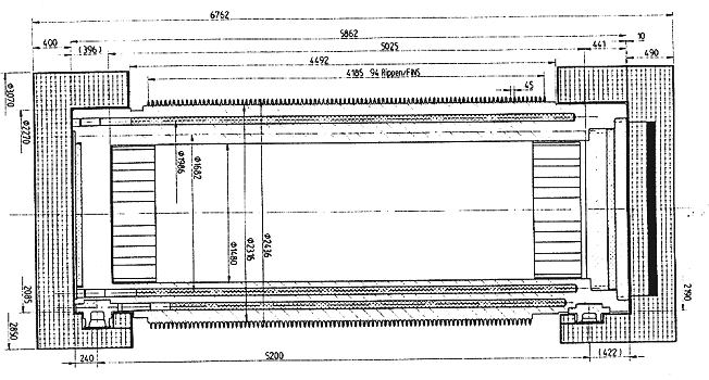
Fig. 1. Transport
configuration.
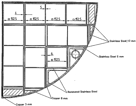
Fig. 2. Basket, cross section.
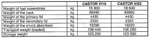
The weights of the CASTOR V/19 (GNS B 98/92) and V/52 (GNB B 110/94) are summarized in Table II.
Table II Mass of CASTOR V/19 and CASTOR V/52 Components
DESIGN CRITERIA
The main mechanical and thermal test resp. accident design criteria defined by the IAEA regulations and the German storage criteria are the following:
| a) mechanical tests |
|
drop tests earthquake, side impact, aircraft crash, gas cloud explosion |
| b) thermal tests |
|
800°C for ½ hour 600°C for 1 hour |
CASK INVENTORY
The casks CASTOR V/19 and V/52 can accommodate the types of fuel assemblies as shown in Tables III and IV.
Table III CASTOR V/19, Fuel Assemblies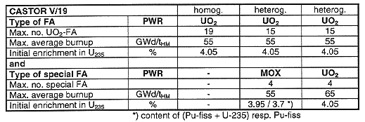
Table IV CASTOR V/52, Fuel Assemblies
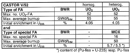
The mass of heavy metal per fuel assembly is 542 kg for the CASTOR V/19 and 187 kg for the CASTOR V/52. The max. allowable heating per cask is about 40 kW.
DESIGN OF THE IMPACT LIMITERS AND STRESS ANALYSIS OF THE CASK BODY
The aim of the impact limiters is to reduce the decelerations on the cask caused by the above mentioned drop tests in such a way that the stresses in the cask remain lower than the allowable values. The analysis is based on the law of energy conservation:

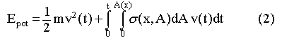
With
Epot potential energy, Ekin(t) kinetic energy in the cask at the moment t, EV(t) deformation energy in the impact limiter at a moment t, m mass of the cask, v(t) velocity at a moment t, (x,A)
local compressive stress in the impact limiter material within an area A with a deformation path x, A(x) local deformation contact area of the impact limiter with a deformation path x, t impact duration up to a deformation x.
Because of the unyielding and rigid surface of the IAEA drop test foundation, the basis for the analysis is that the whole impact energy will be dissipated by plastic deformation of the impact limiter. During the impact process kinetic energy decreases in the same amount that the part of deformation work increases during the impact. The compressive stresses are calculated from the local deformations according to the stress-compression characteristics of the wooden impact limiter which have been investigated by experiments. The compression characteristic of different wood types has been implemented into the software called DROP which is calculating according to the above mentioned model. DROP has been benchmarked by several experimental drop tests. Conservatively the steel coat of the impact limiters has been neglected.
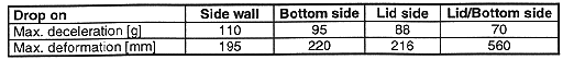
To verify the results calculated with the DROP-code and to get the max. stresses, additional comparisons of the CASTOR V types with experimental results of several drop tests with other, very similar CASTOR casks were made (GNS B 98/92; GNB B 110/94). The results show differences of max. 11 % in the deceleration between the calculation and the experimental drop tests which is within the usual tolerance range of designing impact limiters, especially taking into account the range of tolerances of wood characteristics. The following Table V shows the max. decelerations and deformations of the CASTOR V/19 resp. V/52.
Table V Maximum Deceleration and Deformation of CASTOR V Casks
For the max. deceleration of 110 g the max. bending stress was calculated according to the one-dimensional transverse beam model which has been benchmarked by several drop tests (GNB B 2/93):

with
| max. bending stress; | |
| Mb,max | max. bending moment; |
| W | moment of resistance under consideration of the weakening by the moderator boreholes. |
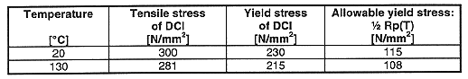
The max. tensile stress of the CASTOR V casks is 81 N/mm2, which is well below the half of the yield stress Rp of the cask material DCI under accident conditions at the design temperature of 130°C (GNS B 98/92; GNB B 110/94) (see Table VI).
Table VI Temperature, Tensile Stress, Yield Stress, and Allowable
Yield Stress Ranges of CASTOR V Casks
MECHANICAL ANALYSIS OF THE FUEL BASKET
The baskets are made of stainless steel, boronated stainless steel or steel with a layer of boronated nickel, aluminum and copper. Boronated steel as well as layers of boronated nickel are used for subcriticality reasons, aluminum and copper for the improvement of heat removal.
The analyses of the fuel baskets are conducted using the ANSYS finite element program. ANSYS has been validated by SANDIA benchmark calculations as well as for comparisons to real drop tests which have been done for several CASTOR casks (R. Diersch et al.). The analyses consist of reviewing the stresses and displacements in the baskets when the loads occur on those orientations which represent the extremes. The max. deformations are 1 mm which has been taken into consideration in the criticality calculations. The integrity of the fuel basket and the positions of the fuel assemblies remain unchanged and criticality safety is sufficiently guaranteed.
The CASTOR V/21 D fuel basket is comprised of 21 square slots allowing for storage of 21 fuel elements. The slots are formed from 7 subassemblies, 4 corner units, 1 center horizontal unit and 2 vertical unit. These assemblies are separated from each other by a small gap (see Fig. 3). Gusset plates are installed longitudinally at a spacing of 500 mm.
The material for the surrounding plates, the inner plates, the outer plates, the corrugated plates, and the gusset plates is WStE 500 (material no. 18937). The inner plates are coated on each side with a layer of boronated nickel. The layer of boronated nickel is neglected in the finite element analysis. The copper profiles are used for better temperature behavior and do not contribute stiffness that will make any significance to the structural integrity of the basket. Therefore these copper profiles are not modeled in the finite element analysis. The IAEA drop test conditions have been calculated for a deceleration of 110 g according to the weight of the cask and the behavior of the impact limiters (see above) for cross sections of the basket in three different orientations: 0°, 45° and 90°.
Since the gusset plates area installed longitudinally at 500 mm spacing, a three dimensional finite element model is required to include the effects of sagging of the fuel elements and the baskets inner and outer plates between the gusset locations. Considering the symmetry between gusset plate locations along the longitudinal axis and the different drop orientations a 250 mm long, full cross-sectional (360°) finite element model has been built.
The maximum Von Mises stresses of the different drop orientations in the basket are 179 MPa for the vertical inner plates and about 150 MPa for the horizontal inner plates (see Fig. 3). The maximum stress in the outer plate of 165 MPa occurs where the inner plates are welded with the outer plate (outer rim of the basket). The maximum stress in the gusset plates is 140 MPa (GNB B 125/96). So, in all cases the maximum stresses are below the yield stress of 284 MPa for the used material WStE 500 (material no. 18937) at 350°C (see Table VII).
Table VII Temperature, Young's Modulus, and Yield Stress of CASTOR
V/21 D Fuel Basket
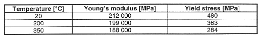
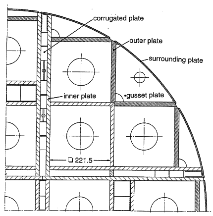
Fig. 3. CASTOR V/21 D Basket, cross
section
THERMAL LAYOUT
The heat dissipation of the CASTOR V packages is performed in a passive manner according to the design principle of all CASTOR casks so that an active heat dissipation system is not necessary, neither under transport nor under storage conditions.
To prove that the max. heat inventory can be dissipated without influencing the contents, the confinement and the shielding, the load case is analyzed with leads to the max. temperatures in the components. For the normal transport conditions, this is the transport of the horizontal cask under a transport hood taking into account the insolation, with the assumption that the cask will not be supervised for one week. During the transport the cask is lying in the transport cradle and equipped with impact limiters under a hood. The calculation has been done in several steps from outside to inside of the cask by calculating
THERMAL CALCULATIONS OF TRANSPORT HOOD AND COMPONENTS
The calculation of the temperatures at the transport hood and the cask surface is based on the determination of the thermal equilibrium between cask, hood and environment taking into account the insolation on the hood surface.
For the formulation of a calculation model, the following conservative assumptions were made:
The temperatures of the hood and the cask surfaces can be determined from energy equilibrium:
| Cask: |  |
| Transport Hood: |  |
| Hood ventilation: |  |
With QI : heat of the inventar,
Qs : insolation to the hood,
QC,CS : heat flow from the cask surface by convection,
QR,CS : heat flow from the cask surface to the hood by radiation,
QR,H : heat flow from the hood to the environment by radiation,
QC,H,I : heat flow from the hood into the wagon by convection,
QC,H,a : heat flow from the hood to the environment by convection,
QL : heat flow from the wagon to the environment by airstream.
The thermal analysis of the basket and the cask body has been done by the benchmarked Finite Element Code TOPAZ2D. For the calculation the following assumptions were made:
The time depending calculations of the heating test were done according to the IAEA regulations and the German regulations for the storage sites. Therefore the load case with the max. temperatures of the stationary calculated temperatures during normal transport has been used. The caloric material properties relevant to the calculation were taken into account in dependency of the temperature. Shielding and confinement must be maintained during the test.
The max. temperatures of the components of the CASTOR V/19 resp. V/52 are calculated as shown in Table VIII.
Table VIII Maximum Component Temperatures of CASTOR V Casks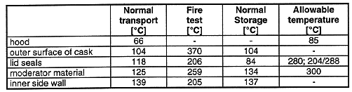
So,
The max. temperatures of the fuel rods are 362°C under normal transport, 392°C at the heating test and 354°C under normal storage conditions. The temperature of 392°C only appears during the heating test for a short while.
CONCLUSIONS
The design of the CASTOR V casks is highly qualified. Due to the above mentioned calculation models which were qualified by several benchmark calculations as well as comparisons to a lot of experiments with other CASTOR casks the time and the costs of developing have been minimized.
The CASTOR V/19 has already been filled in German nuclear power plants and will be transported to the interim storage in the first half of 1997. The filling procedure has been very successful, no difficulties appeared.
BIBLIOGRAPHY
BLG, "Technische Annahmebedingungen für die Einlagerung von Transport- und Lagerbehältern im Transportbehälterlager Gorleben", 1995
R. DIERSCH, R. HÜGGENBERG, G. DREIER, "Verification by Calculations of Shock-Like Loads on Transport and Storage Casks", IMPACT-IV Seminar, Berlin, 1993
GNB B 21/93, "Experimenteller Nachweis der Verpackungssicherheit von CASTOR-Behältern bei Fallprüfungen-Übersichtsdarstellung", GNB 1993
GNB B 110/94, "Antragsunterlagen zum verkehrsrechtlichen Genehmigungsverfahren für den Transport- und Lagerbehälter CASTOR V/52", GNB 1994
GNB B 125/96, "Transportand Storage Cask CASTOR V/21 D Stress Analysis of the Fuel Basket Using the FEM-Code ANSYS®"
GNS B 98/92, "Sicherheitsbericht für den Transport- und Lagerbehälter CASTOR V/19", GNS 1992
IAEA SAFETY STANDARDS, "Regulations for the Safe Transport of Radioactive Material 1985 Edition (As Amended 1990)", Vienna, 1990
RW-TÜV, "Ermittlung von für das Deformationsverhalten diverser Holzarten charakteristischen Kraft- und Energiewerten", Prüfbefund Nr. 451183/01, Essen