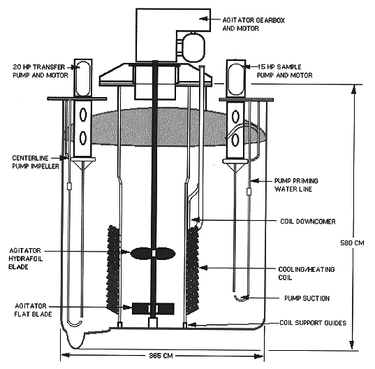
Fig. 1. Typical remote tank with tank top components
David B. Little, James T. Gee, and William M. Barnes
Westinghouse Savannah River Company
Aiken, SC 29808
ABSTRACT
The Savannah River Sites Defense Waste Processing Facility (DWPF) near Aiken, SC is the nations first and the worlds largest vitrification facility. Following a ten year construction program and a 3 year non-radioactive test program, DWPF began radioactive operations in March 1996.
This paper presents the results of the first 9 months of radioactive operations. Topics include: operations of the remote processing equipment, including a discussion of their unique design requirements, remote processing equipment reliability, and decontamination facilities for the remote processing equipment. Key equipment discussed includes process pumps, tele-robotic manipulators, infrared camera, HolledgeTM level gauges and in-cell (remote) cranes. Information is presented regarding equipment failures and related lessons learned. The erosion and corrosion evaluation of the remote equipment at the conclusion of the DWPF test program is also discussed, with special emphasis on agitator blades and cooling/heating coil wear.
INTRODUCTION
In March of 1996 the DWPF began vitrification of approximately 130 million liters of high level radioactive waste into a durable borosilicate glass. This process involves the removal of the waste from carbon steel underground storage tanks, pretreatment of the waste including the addition of borosilicate glass frit within shielded process cells, melting the waste to form a glass mixture and then pouring the mixture into one-half meter diameter and approximately 3 meter high stainless steel canisters. See Defense Waste Processing Facility Radioactive Operations - Part II Glass Making for additional information on the DWPF process. (1)
The DWPF is currently operating a sludge only flow sheet and only the Chemical Process Cell (CPC) equipment is operating. The equipment required to operate the precipitate flow sheet (Salt Process Cell) is currently in a dry lay-up pending completion and testing of the facilities necessary to "pretreat" the precipitate prior to its transfer to the DWPF. The following is a break down of the key equipment in DWPFs remote process cells. Numbers in the parenthesis indicate the number of components currently in operation under the sludge flow sheet. Equipment used during the pretreatment of the radioactive waste include fourteen agitators (10), 51 variable speed pumps (40), 6 heating and/or cooling coils (4), 6 HolledgeTM level gauges (4), 24 motor-operated valves (10) and about 80 other major mechanical, electrical or instrumentation components (65).
Introduction of the waste into the joule heated melter, filling the stainless steel canister with molten glass and moving the canister through the post filling processes utilizes more than 100 pieces of remote equipment. Major equipment includes; one tele-robotic manipulator (1), two canister turntables (2),two canister decontamination chambers (2), one welder (1), one shielded transporter (1) and four canister handling cranes (4).
EQUIPMENT DESIGN
The DWPF "remote" equipment has unique design requirements due to their interface with the radioactive waste within the shielded process cells. Several key design considerations are discussed below.
First, the equipment must be installed and removed remotely (no human assistance at the installation or removal point) using a Main Process Canyon (MPC) crane. This crane, also remotely operated, uses a 515,000 kg, 57,000 kg, 13,000 kg and two 4,400 kg monorail hoists to manipulate the remote equipment within the process area. Ten closed circuit television cameras mounted on the crane are used by operators to position the equipment. The remote equipment is manufactured to engage a remote two-point lifting device into lift lugs built into the equipment. Furthermore, the equipment is counter-weighted to hang plumb when lifted from the lifting lugs to ensure the equipment can be installed into or onto the process vessel. This is accomplished by strategically placing steel or lead weights on the equipment. In some cases, the balancing weight may equal fifty percent of the equipments weight.
DWPF's process vessels are typically 41,000 liter vertical tanks with only top of tank penetrations (see Fig. 1). By only allowing access nozzles on the top of the tank, the potential for loss of radioactive waste due to leaks at tank flanges is minimized. Also, with top only access, the need to de-inventory the tank in order to remove support equipment, such as pumps and agitators, is eliminated. However, this design requirement severely limits the size of the equipment that can be installed on the tank. Tank top space is a premium commodity. Therefore, each piece of remote equipment is assigned a 3 dimensional space envelope. The manufacturer is required to design and construct the equipment to fit in the allowable space while meeting all the design requirements. Thus, many companies must modify their standard design in order to meet the limited space requirements.
Fig. 1. Typical remote tank with tank top components
Another design requirement that often alters the manufacturer's standard design is the limited availability of utilities or support services to the equipment (e.g., cooling water for mechanical seals or oil to lubricate bearings). Utilities or services are provided to the remote equipment through process piping, electrical cables or instrumentation cables. However, just as each tank top component must be remotable with the MPC crane, so must each of the utility or service connections. This is accomplished by building structural supports around the piping or conduit to form a removable "jumper." The jumper is balanced, like the equipment, to ensure it will remain plumb when lifted by the crane. Special remote connectors allow the jumper to interface with the equipment and its through wall utility or service connection. The design and fabrication of these jumpers is extremely expensive and therefore limited to only essential services or utilities.
Materials of construction must be resistant to the process chemistry as well as acid sprays and wash which are used to decontaminate the equipment for the rare occasion when "hands on" maintenance is required, or for the disposal of the equipment after its failure. In the DWPF, 300 series stainless steel and a nickel based alloy (N10276) were chosen for their ability to withstand the effects of the acid washes. Other factors in selecting materials of construction include the materials abilities to withstand high doses of radiation without unacceptable changes to its physical or chemical properties, and its ability to withstand erosion or corrosion from the process chemistry. It is often necessary to move away from the standard materials of construction in order to select a material that will hold up well to the acid wash, while also being radiation resistant.
Thus, many of the DWPFs components are modified or altered significantly from the manufacturers standard construction. This results in equipment failures that are typically seen with prototype or first generation equipment. The performance and reliability of specific equipment is discussed below.
EQUIPMENT OPERATING EXPERIENCE
Pumps
The DWPF utilizes Vertical Cantilever Centrifugal (VCC) pumps to sample, transfer and feed radioactive materials within the process cells (see Fig. 2). Overall pump performance has been very good. Forty pumps are currently operating as part of the sludge only flow sheet. Several of these pumps are in continuous operation with almost 100,000 hours of trouble free operations. The remaining pumps are used for sampling or batch transfer with between 500 and 1000 hours of successful operation. However, two generic problems are currently under evaluation in order to improve the reliability of the pumps.
The transfer pumps will lose suction lift prematurely due to air entrainment from agitation (causes foaming at the fluid surface). This problem was initially identified during the non-radioactive test program. Testing at various fluid levels and agitator speeds confirmed that air entrainment as high as 11% by volume could occur in DWPF's tanks. A typical VCC pump can lose suction lift when pumping a fluid with as little as 2 or 3 percent air by volume. Therefore, to minimize air entrainment, operating procedures were modified to specify tank levels at which agitator speed is reduced or the agitator stopped. (2)
However, at the start of radioactive operations, a second phenomenon was detected that resulted in pump suction lift loss. DWPF personnel determined that small changes in tank fluid temperature (less than 10 degrees Celsius) significantly affect the transfer pump's performance. Attempts to transfer the Sludge Receipt and Adjustment Tank (SRAT) contents to the Slurry Mix Evaporator (SME) were unsuccessful immediately after a process change had been implemented. The process change centered around cooling the vessel's contents during non-processing periods. The fluid's properties changed at the lower temperature which stabilized the existing foam. Over time, the foam was entrained in the fluid so that, regardless of agitator speed, the pump could not maintain a suction lift. In the SRAT, the suction lift was lost within one minute of starting the transfer pump. This problem has been eliminated by increasing the fluid's temperature prior to initiating a transfer.

Fig. 2. Typical cantilever centrifugal remote pump.
The second problem experienced was failure of the priming and suction line on one of the continuous operating pumps. The loads induced by tank agitation (20 Hp agitators) on the approximately 3.5 meter long assembly was greater than calculated by the manufacturer. This resulted in a fatigue failure of the piping at the cross piping supports (See Fig. 2). Since these locations are above the fluid level, air in-leakage below the casing and impeller occurred and resulted in a loss of pump suction lift. This problem is limited to only those vessels with 20 Hp agitators since the priming and suction lines for pumps in other tanks are of a different design. Redesign of the support is underway and modifications will be implemented when a pump is removed from the process cell due to failure.
Motor Operated Valves (MOV)
DWPF has successfully incorporated the use of motor operated valves within the remote process cells. The MOV's are located in process piping jumpers. Electrical power and associated instrumentation (e.g., limit switches) are supplied through a second jumper containing the power and instrument cables. The majority of the MOV's are infrequently operated; typically cycled in response to an abnormal plant condition. Three MOV's are modulating valves in continuous operation. The performance of most MOV's has been acceptable.
During the 3 year test program a design deficiency was detected that affect 6 valves. Testing of motor/actuators for these MOV's (single manufacturer) determined that a significant number of internal parts were not radiation resistance to the extent required by the engineering specification. Several components that were tested failed at exposure levels of 2.0 x 10⁶ RADs.
Three of the MOV's are used to adjust flow to the CPC scrubbers. The use of a MOV was based on the potential for pluggage of the scrubber and therefore the need to increase flow to off-set the higher differential pressure through the scrubber. After several years of operations with the scrubbers (2 years in the test program and 9 months of radioactive operations), no fouling has been detected. Prior to the initiation of radioactive operations the MOV's were positioned to provide a flow rate to the scrubbers that was at the high end of the process flow sheet operating range and the motors were de-energized.
The remaining three MOV's include two drain valves and a diversion valve (3-way valve). These valves were de-energized in their "normal" position. If re-positioning of the MOV is required due to a process upset, then the MOV's will be removed, decontaminated, repositioned and re-installed. Design studies are currently underway to determine a permanent solution to this problem.
Tele-Robotic Manipulator (TRM)
Due to the periodic build-up of glass in the melter pour spout, a tele-robotic manipulator was designed, fabricated and installed to assist with cleaning the pour spout. The TRM has a reach of 330 centimeters and when fully extended is capable of lifting 45 kilograms. The TRM is computer command controlled and has the ability to be pre-programmed to perform some evolutions automatically. It uses stationary and rotary tools (powered by the TRM) to clean the pour spout. It also has a camera mounted at the end of its arm to allow viewing of the pour spout. The TRM like other process cell equipment is remotable using the MPC crane.
Robustness of the unit has been below expectation. However, this is not unexpected since it is a prototype design. All failures have been electrical in nature. Problems experienced by the unit include electrical noise on instrument circuits generated by power cables in proximity to the instrument cables, power cable failures at the manipulator's joints due to wear, and a motor failure due to excessive amperage draws because misalignment occurred within a gear train. These failures have required the manipulator to be removed from the process cell and repaired in the remote equipment maintenance cell. No repetitive failures have been detected in the manipulator during nine months of operation.
HolledgeTM Level Gauges
In vessels containing the radioactive slurry, level and density measurements are determined by the use of four HolledgeTM sensors mounted at different levels within the tank. These sensors are contained in a remote jumper. The use of the HolledgeTM sensor instead of a standard bubbler is based on the need to know density as well as level with an instrument that will not plug. Testing determined that a standard bubbler will become plugged within 24 to 48 hours of operation in the radioactive sludge. This is due to the sludge drying on the wall of the bubbler at the air to sludge interface and building up until it has bridged over the cross section of the pipe. The HolledgeTM design uses a membrane sensor to measure the pressure exerted by the height of the fluid covering the sensor. The membrane eliminates the air to fluid interface and thus the drying action that plugs a standard bubbler.
Performance of the HolledgeTM level gauge in most process tanks has been a complete success. However, in the SME, two level gauges have failed in the first 9 months of operation. The second gauge failed after only two months of operation. The mode of failure has not been determined, but both level gauges had an initial sensor fail (a different sensor in each gauge) with the other sensors following in rapid succession. Alternate designs are under evaluation to determine if a better technology is available for this specific application.
Infrared (IR) Camera
DWPF utilizes an infrared camera to determine glass height within its canisters. Stainless steel targets are located in front of the canister at glass filling heights from about 200 to 250 centimeters. These targets remain at the process cell's ambient temperature during canister filling. As the canister is filled, its temperature increases from ambient to about 800 degrees Celsius. This provides excellent color contrast on the IR camera and permits accurate level determination (within 10 centimeters). Use of the IR camera ensures the canister is filled to 80% of its volume, which is a requirement of the Department of Energy's Waste Acceptance Product Specifications.
The life expectancy of the camera is about 3000 hours of operation. Two camera failures have occurred since the start of radioactive operation. The first camera failed soon after the start of radioactive operations as was expected based on its total number of operating hours. The second camera failure also occurred after its expected operating life. In both cases the cameras were operating during the entire time canisters were being filled (typically 20-30 hours per canister). To extend camera life, it is now utilized only at the start of filling a canister and completion of a canister (typically 4 -5 hours per canister). When the IR camera is off, a load cell measuring canister weight in pounds is used to track progress in filling the canister.
In-Cell Cranes
Four in-cell cranes are used in support of the process, primarily in the movement of canisters. Three of the cranes have a 22,000 kg capacity and the last has a 33,000 kg capacity. The cranes are completely remotable. The trolley and bridge can each be removed from their installed location with the MPC crane. Furthermore, individual components on the crane (e.g., bridge drive, trolley drive and hoist motor) can be remotely removed. Crane performance has been excellent over the first 5 years of crane operations. However, one problem was detected that required the cranes to be removed from their operating location after the initiation of radioactive operations.
The failure was generic in nature and required a modification to all in-cell cranes. Bolts that attach the bridge and trolley motors to their respective gearboxes were failing due to overloading of the bolts. Material testing and re-calculation of the torque produced by the motor determined that the bolts were undersized for the load. The flange between the motor and gearbox was welded together to provide the additional strength required to prevent failure of the bolts. After their re-installation, no additional problems have been detected.
DECONTAMINATION FACILITIES
DWPF contains two process cells for remote equipment decontamination and maintenance. The first cell is the Remote Equipment Decontamination Cell (REDC). This cell is lined with 95 millimeter thick stainless steel plate on the walls and floor. Clayton CleanersTM and Sellers JetsTM are used to decontaminate the remote equipment. Two Electro-Mechanical Manipulators (EMM's) and up to 8 Master-Slave Manipulators (MSM's) are available to hold and direct the Clayton Cleaner and Seller Jet wands inside the cell. Stands are available to hold the equipment during decontamination process. Equipment that has been submerged in the radioactive waste (e.g., agitator blades, pumps, etc.) may be soaked in a tank located in the cell. Equipment is also available to decontaminate the inside of a process tank or the external surfaces of a melter after its failure. Four lead glass and oil filled shield windows are available to view the inside of the cell.
The facility is designed to use four basic decontamination fluids. Steam, 50% nitric acid, 10% oxalic acid and detergent are used to clean the equipment. The nitric acid, oxalic acid and detergent are made-up outside the vitrification building and pumped by canned motor pumps to holding tanks located at the two cells. Additional pumps are available to pump the decontamination fluids directly into the cell. The Clayton CleanersTM and Seller JetsTM may also use the fluid directly from the holding tanks.
Contamination levels on the equipment removed from the various process cells range from undetectable to 25 MRAD/HR/100 CM2 beta-gamma. In all but the most recent cases, steam alone has been adequate to remove the contamination. However, equipment decontaminated within last 30 days has required nitric acid to reduce the contamination levels to acceptable levels. No personnel contamination cases have occurred during the first 9 months of operation. No contamination has been found outside posted contamination areas.
After the equipment is decontaminated, it is relocated to the Contact Decontamination and Maintenance Cell (CDMC). Once in the CDMC, additional surveys can be conducted to determine more precisely the contamination and radiation levels. The CDMC also has a stainless steel liner on its floor and walls. It also has the same equipment and decontamination fluids available to decontaminate equipment as is found in the REDC. The CDMC has three shield windows.
The CDMC is designed to allow personnel to enter and perform hands-on maintenance on equipment in the proper protective equipment. Entry into the cell typically requires a full body plastic suit with forced air supply. Breathing air can be supplied to 6 individuals at one time. Maintenance has been performed on numerous pieces of contaminated equipment during the 9 months of radioactive operations. Highest level of transferable contamination found in the CDMC to date is 17 MRAD/HR/100 CM2 beta-gamma. This was found on the tele-robotic manipulator during its last maintenance period.
The CDMC is designed to allow testing of most pieces of equipment after repairs are completed. For example, a 3800 liter run-in tank is available to test run pumps after maintenance. The Mechanical Equipment Test System (METS) will automatically run the pump for up to 24 hours and measure pump flow, pump discharge pressure, motor power, motor and pump vibration and motor and pump bearing temperatures. The METS will shutdown the equipment if specific parameters are exceeded during the run-in period.
Radiation exposure levels remain extremely low due to the sludge only flow sheet (lack of Cesium). Rates as high as 40 millirem/hour at 30 centimeters have been recorded during work on the in-cell cranes. Also, personnel radiation exposures have been within radiological guidelines for all plant evolutions.
MATERIAL EVALUATION PROGRAM
A materials evaluation program was performed to evaluate the material degradation mechanisms in remote process equipment. The scope of the program included selected critical feed preparation equipment located in the process area. The baseline portion of this materials evaluation program was completed in 1992. Process equipment inspected included: process vessels, pumps, agitators, and coils. Various NDE (non-destructive examination) techniques were used during the baseline and subsequent follow-up inspections, including: ultrasonic testing (UT), visual (direct or video probe), radiography, penetrant testing (PT), and dimensional analyses. The final equipment inspections were performed in the fall of 1995 after completion of the test program. (3)
The DWPF process equipment will be subjected to two basic wear phenomena, chemical corrosion and abrasion due to glass frit particles. For process slurries, particularly those with glass frit particles (e.g., slurry mix evaporator), the overall wear rate will be determined by the combined effects of both abrasion and corrosion. This phenomena will be referred to as "erosion/corrosion." Wear associated with erosion is characterized by the localized removal of the protective oxide layers by abrasion. Since such oxide layers on the material surfaces provide corrosion protection, their continuous removal would open up the material structure to chemical corrosion. Given the harsh chemical environment encountered in the DWPF process (e.g., halides, mercury, sulfates, elevated temperatures, etc.), corrosion was also thought to be of considerable concern.
EQUIPMENT INSPECTIONS - MATERIAL PERFORMANCE
Chemical Process Cell (CPC) - Tanks and Vessels
CPC vessels include the precipitate reactor bottoms tank (PRBT), sludge receipt and adjustment tank (SRAT), slurry mix evaporator (SME), slurry mix evaporator condensate tank (SMECT), and melter feed tank (MFT). These tanks contained liquids or slurries that were acidified through the process and contained potentially corrosive species. With the exception of the SMECT, all of the CPC vessels were fabricated from alloy N10276. This nickel based alloy is expected to be highly resistant to localized or general corrosion under the expected service conditions. The SMECT, fabricated from S31603 stainless steel, would also be highly unlikely to corrode given the dilute nitric acid chemistry of the process fluid.
The CPC vessels were examined through the use of visual observations and external UT measurements. Statistical and graphical presentations of the UT data comparing wall thickness between the original baseline and pre-radioactive operation inspections demonstrated that none of the CPC vessels had experienced significant wall thinning (i.e., erosion/corrosion) during the non-radioactive test program. Using vessel inspections and corrosion coupon evaluations, it was concluded that CPC process vessels will last the life of the DWPF facility (i.e., 20-30 years).
Removable Process Cooling/Heating Coils
Removable coil assemblies from four tanks (SRAT, SMECT, SME and MFT) were inspected. The coil assemblies are of a similar design. The SMECT cooling coils are constructed of S31603 stainless steel, while the other coil assemblies are constructed of alloy N10276. The SRAT and SME coil assemblies incorporate both heating (steam) and cooling coils, while the SMECT and MFT coil assemblies provide only cooling.
The coil assemblies were examined through the use of visual observation and ultrasonic thickness (UT) measurements. Coil assemblies for the SRAT and SMECT, which are used in process fluids without glass frit particles, showed no evidence of erosion/corrosion. The SME and MFT coil assemblies which are exposed to slurries with glass frit showed significant evidence of localized erosion. The patterns of wear were the same for both, although the SME coils experienced greater wear than the MFT coils.
Significant erosion on the SME coil assembly occurred in two general areas. The first area was at the bottom portion of the downcomer pipes (which extends below the coil itself). The downcomers were worn smooth with a high degree of polish. Wall thinning of up to 40% was measured ultrasonically on the downcomer pipe for the inner coil. Similar measurements on the MFT downcomer pipe revealed 15% wall thinning. The second area was the lower coil support structures (4 locations) for all three coils. The support structures had significant erosion patterns with a loss of 50% or more of the support member cross section in some places (see Fig. 3).
UT thickness measurements were taken at locations on the SME and MFT coils and showed no significant wall thinning. Based on this data and visual inspections of the coils, it was concluded that significant corrosion of the coils had not occurred.
The observed wear patterns on the SME and MFT coil assemblies are consistent with the predominant flow patterns in these tanks. An agitator located inside the coils provides constant mixing of the tank contents. The lower blades are oriented vertically to drive the slurry outward, while the upper blades are positioned to establish a downward flow. Together, the upper and lower blades set up a circulation pattern that includes rotation around the tank, upward motion outside the coils, and downward motion inside the coils. With the lower agitator blades near the bottom of the cooling coils, the downcomers and lower support structures are located in a region of relatively high flow velocity and turbulence. The presence of glass frit in the SME and MFT distinguishes these two coil assemblies from the SRAT and SMECT coil assemblies. With no abrasive material present in the other two tanks, those coil assemblies experienced no significant erosion.
Based on the lack of degradation observed on the SRAT and SMECT coils, no significant limitations to their service life were identified. They are expected to continue operating for the life of the facility. Erosion due to the glass frit is expected to limit the service life of the SME and MFT coil assemblies, although implemented repairs should extend the service life of this equipment (i.e., 2-5 years).
Sample Pumps
Vertical cantilever centrifugal sample pumps from the SRAT, SME, and MFT were inspected for evidence of erosion and/or corrosion. The pumps are used to collect samples for analytical analysis from their respective process vessels. The SRAT sample pump's impeller and impeller casing were fabricated from CW7M, a cast version of alloy N10276. The pump casings and impellers from the SME and MFT were fabricated from cast alloy R30006. All other sample lines were constructed from alloy N10276. Visual and UT inspection of all the pumps did not reveal any evidence of serious corrosion or erosion. Overall the SME, SRAT, and MFT sample pumps were in excellent condition and should not be adversely affected by either erosion or corrosion over their design life.
Agitator Blades
The agitators from the SRAT, SME, and MFT were removed and evaluated for evidence of erosion, corrosion and cracking. Agitator blade assemblies, constructed of alloy N10276, are used in the feed processing vessels to adequately mix the viscous frit/sludge/slurry mixtures for proper sampling and processing. They consist of two sets of blades, an upper set of curved hydrofoil blades (three blades) and four lower flat rectangular blades. Design life of the agitators is five years. Nondestructive examinations (NDE), consisting of ultrasonic thickness testing (UT) and liquid penetrant testing (PT) were performed to identify and quantify the degree of general corrosion, erosion and cracking resulting from 12-18 months of operation.
The SRAT agitator is not exposed to erosive glass frit particles, so erosion was expected to be minimal. Visual inspection showed minimal erosion on the back side of the lower blades near the attachment tabs. No evidence of corrosion or cracking was observed. Therefore, this agitator is expected to perform satisfactorily for at least five years.
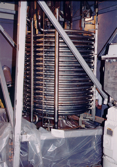
Fig. 3. Lower portion of the SME coil assembly showing coils downcomer pipes and support structure.

Fig. 4 Back side of lower SME agitator blade showing severe wear of the blade at corners and upper edge of the blade near the hub
The SME's mixture is more abrasive than those in the SRAT. Therefore, both erosion and corrosion are of potential concern for the SME agitator. Minor erosion was observed on the leading edge and tip of the upper hydrofoil blades. Deep wear scars, approximately 50% through wall, were observed on the back sides of the lower agitator blades (see Fig. 4). Severe erosion of the blades was observed at the corners of the attachment tabs. Only a slight rounding of the edges was visible on the front sides of the lower blades. No evidence of cracking or significant corrosion was observed on any of the blades. The SME agitator blade, as originally designed, experienced severe degradation and will not survive more than two years of continuous operation. Erosion of the SME agitator as a result of the glass frit slurry had been expected, based on inspection of similar equipment at pilot testing facilities. A spare unit with a new blade design (i.e., increased use of W73006 hard-face overlay coating to mitigate erosion) had been procured as a contingency and was installed prior to radioactive operations.
Wear patterns, similar to those on the SME agitator blades were observed on the MFT agitator blades. However, the wear was significantly less. No evidence of corrosion or cracking was observed. The MFT agitator should perform satisfactorily for its five year design life.
ACKNOWLEDGMENT
This paper was prepared in connection with work done under Contract no. DE-AC09- 89SR18035 with the United States Department of Energy.
REFERENCES