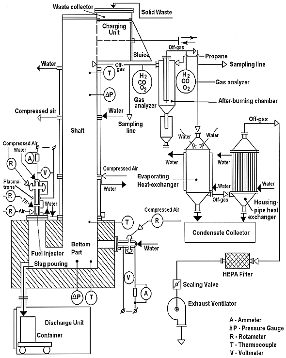
Fig. 1. Flow sheet of experimental
plant based on shaft furnace.
Sergey A. Dmitriev, Feodor A. Lifanov, Sergey V. Stefanovsky,
Alexander E. Savkin, Igor A. Knyazev, Michael A. Polkanov, Tatiana N.
Lashtchenova,, Sergey M. Golobokov
SIA "Radon", 7th Rostovskii
per., 2/14, Moscow, 119121 Russia
Serge Merlin, and Patrice Roux
SGN Reseau Eurisys
1 Rue des Herons Montigny le Bretonneux
78182 St Quentin Yvelines Cedex
France
ABSTRACT
Liquid slagging incineration tests with simulated low-level solid waste marked with 137Cs were performed. Two surrogate compositions were treated in a shaft furnace-based plant heated with plasma-fuel burners. First waste composition contained mainly cellulose, and the second one - polyethylene. Wastes were fed both each separately and alternately. The main process variables were as follows, input electric power 50.2-66.7 kW, total heat supply - 129.6-211.2 kW, temperature in melting zone - 1400-1500°C, off-gas temperature - 500-600°C; waste capacity - 21.6-29.7 kg/h, slag productivity - 4.73-8.56 kg/h.
INTRODUCTION
Incineration of burnable radioactive waste reduces waste volume by a factor of up to 100 (1). Gases and ash are formed at waste incineration. Incinerator ash is dusting, unstable, and low chemically durable material to be subjected to additional treatment for stabilization (2). Besides unstable slag, another disadvantages of chamber incinerators are as follows,
Ten years ago a new technology for unsorted waste treatment was proposed. It was high temperature shaft furnace with liquid slagging (3). Investigation of waste treatment process in shaft furnace has shown that method reduces significantly above-mentioned disadvantages. This furnace is able to treat both organic and inorganic wastes such as glass, ceramics, construction materials, garbage, metal reinforcement, etc. As it has been demonstrated elsewhere, liquid slagging is the most significant advantage of this furnace because slag does not require additional treatment. It is solid, chemically durable material suitable for long-term storage or final disposal (4).
According to Contract between SGN Corp. and SIA "Ration", a tests with incinerator based on shaft furnace were conducted. Waste composition was specified by SGN.
The purposes of given work were
SHAFT FURNACE CHARACTERIZATION
The tests were performed with experimental plant with specified waste capacity of 35 kg/h. The plant consisted of shaft furnace and off-gas purification system. The shaft was water-cooled. Shaft overall dimensions were 150 mm in diameter, 1500 mm in height. The bottom part dimensions were 500x200x200 mm. Fuel-plasma and plasma heaters were applied as heat sources in the bottom part of the furnace. Process flow sheet is shown on Fig. 1.

Fig. 1. Flow sheet of experimental
plant based on shaft furnace.
The basic technical characteristics of the bottom part of the plant were specified as follows
| • temperature in melting zone,°C | 1400-1500 |
| • off-gas temperature,°C | 500-600 |
| • off-gas flow rate, m3/h | 100-150 |
| • total power of heat sources, kW | 50-70 |
| • the number of plasmatrones | 2 |
| • electric arc current, A | <180 |
| • efficiency | 0.6-0.7 |
| • fuel flow rate, kg/h | 2-4 |
WASTE COMPOSITION
Approximate waste compositions specified by SGN are given in Table I. In order to perform experiments, two waste compositions were prepared.
Table I Waste Compositions

In actual waste compositions specified metal, filter materials, and glass were introduced as electric cable (contained latex and metal), chemical dishes and borosilicate glass breakage, and dolomite meal. Glass was also used as fluxing agent in order to reach suitable slag properties, and liquid slagging.
PRELIMINARY EXPERIMENTS
Taking into account that radionuclides volatilization and liquid slagging maintenance are the most important problems, a special investigation was carried out.
Cesium is the most volatile element and volatilization of cesium
radionuclides causes greatest problems at nigh temperature treatment of
radioactive waste. There are some species, mainly acid oxides such as SiO2,
A1203, P205 as well as uranates
(5), which are able to suppress cesium volatilization. Silicon, aluminum as well
as phosphorus compounds are usual components of solid wastes. Significant
quantity of uranates may be presented in the case of treatment of radioactive
wastes containing actinides. Radon experience has shown that Radon chamber
incinerator ash concentrates
![]() -emitters,
mainly actinides, and ash specific activity on
-emitters,
mainly actinides, and ash specific activity on
![]() -emitters
and
-emitters
and ![]() -
-![]() -emitters
are comparable. Occasionally, ash specific activity on -emitters may be by one
to two orders of magnitude higher than on
-emitters
are comparable. Occasionally, ash specific activity on -emitters may be by one
to two orders of magnitude higher than on
![]() -
-![]() -emitters
(6). Under this conditions the effect of uranates on suppress of cesium
volatilization may be exhibited. Taking into account the great effect of
temperature on cesium volatilization and waste layer filtration ability it is
necessary to create temperature gradient over shaft height. In the upper pan of
the shaft physical condensation of volatile cesium compounds should take place.
In the bottom pan of the shaft chemical fixation of cesium and its compounds
should occurs.
-emitters
(6). Under this conditions the effect of uranates on suppress of cesium
volatilization may be exhibited. Taking into account the great effect of
temperature on cesium volatilization and waste layer filtration ability it is
necessary to create temperature gradient over shaft height. In the upper pan of
the shaft physical condensation of volatile cesium compounds should take place.
In the bottom pan of the shaft chemical fixation of cesium and its compounds
should occurs.
Investigation on slag properties prediction was carried out as well. One of the main characteristics of silicate melts being important for liquid slagging are temperature range of viscosity required at predetermined operating temperatures. According to reference data, liquid slagging temperature is ranged between 20 and 50 Pa•s (7). However, it is clear from experience, there was not satisfactory slag outflow in spite of low molten slag viscosity. Determination of normal liquid slagging temperature is impeded due to no any characteristic point as we have dealings with slags solidifying at cooling in vitreous state. More detailed knowledge of slag viscosity and its dependence on chemical composition to ensure liquid slagging are required.
Pre-estimation of slag properties - chemical composition relation based on different role of base and acid oxides was developed. It is connected to anion structure coefficient value being equal to oxygen to silicon ions numbers ratio
 (1)
(1)
where n - portion of aluminum ions being able to substitute isomorphously for silicon ions in anion structure forming alumino-silico-oxygen anions.
Given technique possesses sufficient degree of detail and reliability in order to adjust chemical composition of final product and to reach required physical and chemical properties. A portion of aluminum ions able to substitute for silicon ions in complex anions may be determined from spectroscopic data taking into account that only four-fold coordinated aluminum ions can form such anions and spectral characteristics of four- and six-fold coordinated aluminum ions are significantly different (8).
Choosing optimal slag compositions, taking into account a features of radiochemical technology, considerations were chosen as follows
Experiments were conducted with waste whose composition was varied as follows (wt.%):
| • paper | 10-15 |
| • textile | 15-20 |
| • wood | 5-10 |
| • polymers | 15-20 |
| • rubber | 5-10 |
| • metal and alloys (scrap) | 10-15 |
| • heat isolation, glass breakage | 10-15 |
| • soil | 5-10 |
Moreover, ash residues with compositions (wt.%) listed in Table II were examined. Depended on base or acid properties are predominant for slag, different additives are required.
Table II Compositions of Ash Residues from Radon Fuel Chamber
Incinerator

EXPERIMENTAL PROCEDURE
The furnace shaft was pre-heated to reach inner lining temperature of 1300°C. Waste was packed in paper bags with 400-600 g by mass. These bags was fed into the shaft so that waste column in the shaft was formed. Further, bags was fed with rate determined from experience to ensure permanency of waste column height in the shaft. Melt was poured every 1.5 hours counting from feeding start.
Slag viscosity was measured using IVUS-1 device (designed at Ration). Slag density and porosity were determined by hydrostatic weighing in water. Real porosity was calculated as
 (2)
(2)
where Pr is real porosity, D is density, g/cm3; S is specific gravity, g/cm3.
After slag pouring and cooling containers with slag were cut and taken a pictures.
During the test off-gas flow rate was measured and gas composition was analyzed. Off-gas flow rate was measured with pneumometric tubes and micromanometer. Volume activity and weight concentration of aerosols in off-gas were determined by internal filtration technique. N2 concentration in off-gas was measured by photocolorimetric method, and CO, H2 and CO2 concentrations were determined by chromatography.
Sodium and cesium leach rates were measured according to IAEA technique at room temperature (9).
TEST RESULTS
Preliminary tests has demonstrated key possibility to treat a waste specified by SGN in the shaft furnace according to applied technology.
Three tests with SGN waste with duration 8 hours each were performed. Total test duration was 45 hours (including starting time). 350.5 kg of waste (W1 and W2 types) were processed and 79.1 kg of slag were collected in containers. 271.4 kg of waste have burnt up and they have been transformed in gaseous phase. 30 kg of them were lost with off-gas as aerosols. Periodic visual inspection of operation surface of roof, wall and bottom refractories has not indicated their appreciable corrosion with the exception of refractories contacted with melt.
Radon specialists did not work with waste containing such great quantity of polyethylene and PVC and had no sufficient experience at such waste treatment. It has been decided to change over the cooling of the middle part of the shaft from water to air cooling to avoid an adhering of molten polyethylene and PVC on the inner walls of the water-cooled shaft and shaft clogging. Air cooling increases temperature on the inner wall of the shaft compared to water cooling. In all cases liquid slagging was unimpeded. Slag temperature in the pouring zone reached 1350-1400°C. Melt had viscosity and flowability suitable for unimpeded removal and pouring into containers and filling of whole volume of containers.
The main attention was paid to
Variations in aerosol concentration during the tests at shaft outlet and after-burning chamber outlet are shown on Fig. 2. Off-gas compositions at different waste treatment at shaft outlet are given in Tables III and IV. Total loss of aerosols was 6.4 wt.%.
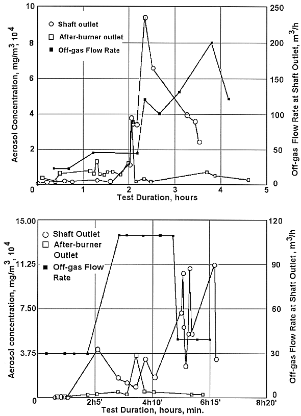
Fig. 2. Aerosol concentration at
shaft and after-burner outlet, and off-gas flow rate at shaft outlet at
treatment of W1 and W2 wastes fed alternatively (top) and separately (bottom).
Table III Off-gas Composition at Treatment of W1 and W2 Wastes Fed
Alternately

Table IV Off-gas Composition at Treatment of W1 and W2 Wastes Fed
Separately

After the bringing furnace to stable operating conditions independently of waste type, temperature conditions were also stable without any deviation from normal operation. Unlike separate W1 and W2 waste treatment alternating feeding of W1 and W2 waste resulted in significant variation of underpressure. It is caused by high polyethylene content in W2 waste Polyethylene is known to be stable in inert atmosphere up to 290°C. At higher temperatures it decomposes with formation of resinous and gaseous products. In the presence of oxygen thermal destruction of polyethylene is significantly expedited. Taking into account that gaseous phase temperature in the bottom part of furnace under operating conditions reaches 1700-1800°C, underpressure variation becomes explicable. It can be avoided by averaging polyethylene feeding. Therefore gas release at thermal destruction of polyethylene should be constant in time and should not influence on stability of underpressure profile in the shaft.
Test with Wastes W1 and W2 Fed Alternately
35 and 40.5 kg of W1 and W2 wastes respectively were processed and 14 kg of slag were poured. Slag composition and properties are given in Table V.
Table V Slag Chemical Composition and Main Properties
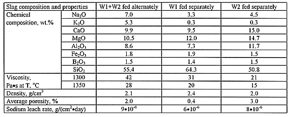
Figure 3,a demonstrates vertical cut of container filled with slag produced at W1 and W2 wastes treatment fed alternately. Two discharges were performed. In the upper part of the ingot (35-55 and 115-130 mm for each discharge respectively) porous zones are appeared. Vigorous pores formation in these zones is caused by two reasons. The first one is slag non-uniformity arose from homogeneous melt solidification. This type of chemical non-uniformity connected to slag solidification was observed in all ingots produced at slow cooling as gas release is facilitated at ingot growth from bottom to top due to elimination of energy barrier of phase separation. It results in formation of gas cavities. The second reason is the falling of molten polyethylene in container together with last portions of slag. Active gas release at polyethylene decomposition is the reason of pores formation.
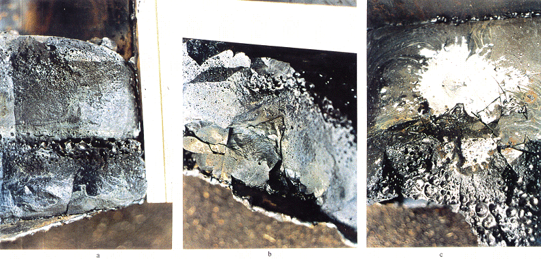
Fig. 3. Pictures of poured slags.
a-Vertical cut of slag ingot produced at W1 and W2 wastes treatment fed
alternately
b-Vertical cut of slag ingot produced for two discharges of W1
and W2 waste slags.
c-Top view of container shown on Fig. 3b.
Pictures
comprise areas 15x20 (a), 12x17 (b) and 15x20 (c) cm, respectively.
Slag porosity in the middle part of each ingot (15-25 and 80-95 mm) is 0.9%. In the upper part of the first (40-55 mm) and second (115-140 mm) discharges the porosity is 8.1 and 2.9% respectively. Such significant difference of porosity values is caused by as follows. When the second discharge was carried out, polyethylene still remained on the surface of slag poured at the first discharge which was not gasified until the beginning of the second discharge. Contact of the molten slag with polyethylene resulted in vigorous gas release and cavities formation.
It is seen good crystal structure of the slag whose solidification was started in the lower zones both first and second discharges especially expressed brightly in the first drainage.
As seen from Table V, sodium leach rate from solidified slag is lower than 1 * 10-5 g/(cm2.day). It corresponds to level of leach rate from borosilicate glasses.
Test with wastes W1 and W2 fed separately
118.6 kg of W1 waste and 30.5 kg of W2 waste were processed, and 33 and 8.1 kg of slag, respectively, were poured. Slag compositions and main properties are given in Table V.
Vertical cut of container filled slag, where two discharges were carded out, is shown on Figure 3 ,b. The first discharge was carried out after WI waste treatment and the second discharge was carried out after W2 waste treatment. The lower part of ingot (first discharge) is nearly fully crystallized. Its porosity is negligible low (see Table V). The upper part of ingot is insignificantly crystallized. Slag porosity ranged between 1.1 (in the middle part) and 4.5% (in the upper part) - averaged value is 3.0% - see Table V. Relative high porosity in the upper part of ingot is connected to the presence of molten polyethylene.
Figure 3, c demonstrates top view of container shown on Fig. 3 ,b. The spot of non-oxidized aluminum solidified as metal is clearly discernible. This spot has clearly contoured irregular boundaries characterizing the fallen spot. Therefore, aluminum was poured by the latest when the whole slag was already discharged rather then came to the surface by floating in container. Aluminum and slag are known not able to be intermixed.
In the lower part of cut ingot specific crater-like formations are discernible. This is upper part of the second discharge where molten polyethylene has been poured with the latest portions of slag from the bottom part of the shaft.
Slags are chemically durable (see Table V).
Underpressure profile was maintained stable during the process at treatment both W1 and W2 wastes.
Test with W1 waste marked with 137Cs
Before the operation with W1 waste marked with 137CS, 27 kg of simulated waste W1 and 5 kg of simulated waste W2 were treated and 6 kg of slag were poured. Molten slag was poured directly before the feeding of waste containing marker to separate 137Cs in the latest discharge. 50 kg of W1 waste marked with 137CS were processed. Total activity of this feed was 6.41-106 Bq. 10 kg of slag were produced.
Radioactive cesium concentrations in off-gas are shown on Fig. 4. Cesium loss in gaseous phase was 1.7.106 Bq that corresponds to 26% of total activity. Taking into account background concentration, real cesium loss was 24%. Background value arose from preliminary treatment of incinerator ash with great specific activity.
| Cesium retention degree in slag is 72% of total fed activity. So, cesium balance is | ||
| • Feed | 6.410*106 Bq | 100% of total |
| • Slag | 4.615*106 Bq | 72 % |
| • Los with off-gas | 1.538*106 Bq | 24% |
| • Retention inside the furnace | 0.257*106 Bq | 4% |
| Average specific activity of slag samples was 4.62, 105 Bq/kg. Slag produced has low leach rate of cesium - < 1 * 10-5 g/(cm2•day). | ||
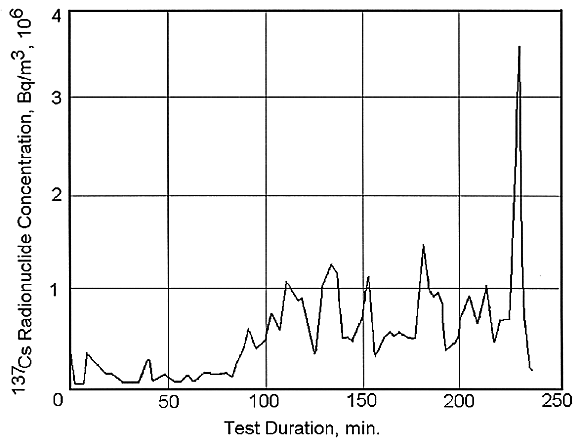
Fig. 4. Variation on radioactive
cesium concentration in off-gas during the test.
Heat Balance
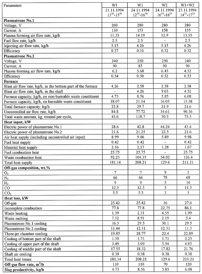
Plasma-fuel heaters parameters and main process variables are given in Table VI. Heat balance was summarized by taking into account of combustion heat of burnable waste constituent. Efficiency of plasma-fuel heater No. 1 was calculated in view of heat loss for the fuel insert cooling. The basic heat supply is caused by input power of plasma-fuel sources of heating.
Table VI Summarized Data of Heat Balance
CONCLUSIONS
REFERENCES