Shogo Okane, Kazutoshi Miyajima, Takeo Mimori
Japan
Atomic Energy Research Institute
Ibaraki,Japan
ABSTRACT
JAERI's Reprocessing Test Facility (JRTF) had been operated from 1968 to 1969. The first PUREX reprocessing test of spent fuel in Japan was carried out successfully by reprocessing the spent U/A1 metal fuel from Japan Research Reactor 3 (JRR-3) and about 200g of Pu was recovered.
About 70 m3 of liquid waste was generated from the reprocessing tests. The design and manufacture of the treatment apparatus for the spent solvent (30%TBP-n-dodecane) had been carried out from 1992 to 1993. 1.2 m3 of the spent solvent had been treated from 1994 to 1995.
The treatment system of the spent solvent consists of two parts; a washing apparatus and an incineration apparatus. The washing apparatus removes Pu from the spent solvent by washing with alkaline solution. After the spent solvent and the calcium octylate were mixed , the mixed solvent was treated by the incineration apparatus. The incineration ash is solidified in cement ,canned ,and stored at the JAERI's Radioactive Wastes Treatment Facility (JWTF).
As the results of these treatments, the following items were proved.
INTRODUCTION
In JAERI, development of treatment technology for TRU waste has been carded out since 1984 using various radioactive liquid waste stored in the JRTF.
The treatment technology for the spent solvent was developed by JAERI under a contract with the Science and Technology Agency.
Results of the incineration treatment for the spent solvent are described in this paper.
THE TREATMENT SYSTEM OF SPENT SOLVENT
The treatment system of the spent solvent consists of two parts; a washing apparatus and an incineration apparatus.
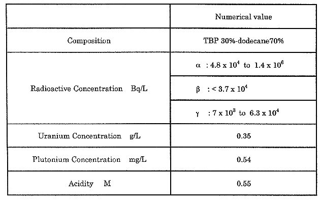
The treatment system of the spent solvent is shown in Fig. 1 and the character of the spent solvent is shown in Table I. In treatment process, the spent solvent is mixed with alkaline solution "sodium carbonate" in the washing tank. After settling, the mixed solution is separated into the washed spent solvent and the spent washing solution. Then the spent washing solution including almost Pu is separated into supernatant and sludge by flocculation process.
The supernatant including
![]() •
•
![]() nuclides
is transported to the JWTF. The sludge is treated by calcination or
vitrification in the JWTF and transported to the JWTF as
nuclides
is transported to the JWTF. The sludge is treated by calcination or
vitrification in the JWTF and transported to the JWTF as
![]() solid waste.
solid waste.
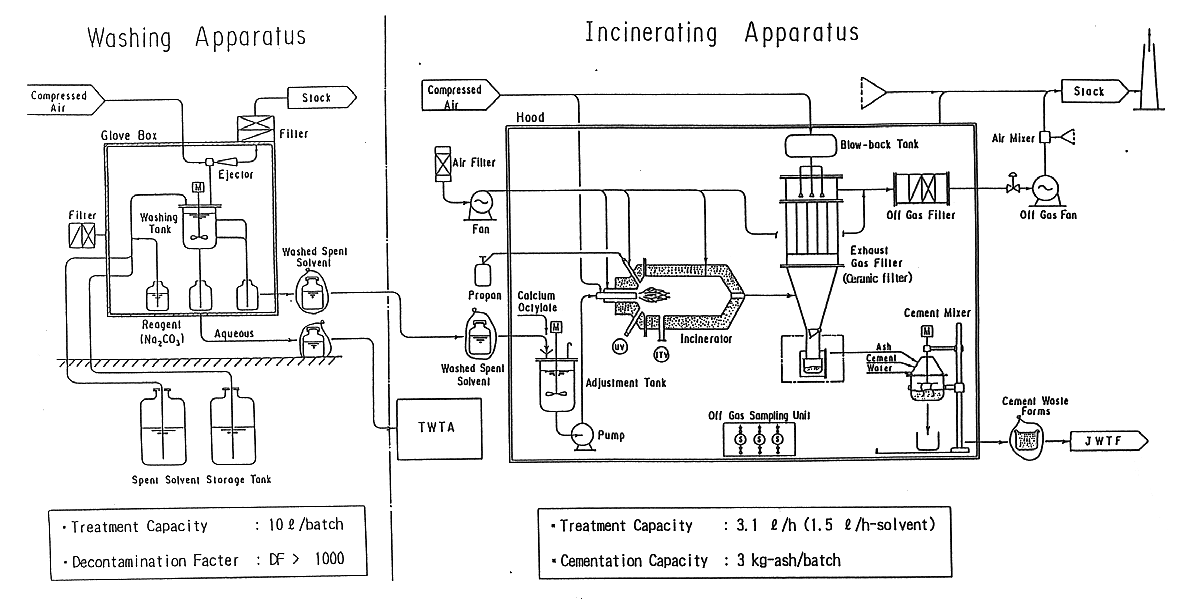
Fig. 1. Flow diagram of spent solvent
treatment system.
Table I Character of the Spent Solvent
WASHING TREATMENT APPARATUS
The washing treatment apparatus consists of a washing tank with a mixer and an ejector vacuum system. This apparatus is installed in the grove box (capacity of 1m3). The washing treatment capacity is 10L spent solvent per batch.
THE WASHING TREATMENT PROCESS
10L spent solvent was pumped up to the washing tank from the storage tank by the ejector. 0.3M-10L sodium carbonate was added to 10 L spent solvent. After a 30 minute mixing and 1 hour settling, the mixed solvent was separated into the washed spent solvent (organic layer) and the spent washing solution (aqueous layer). Pu in the spent solvent moved to the spent washing solution.
The
![]() •
•![]() •
•
![]() radioactive concentration of the washed spent solvent and the spent washing
solution were measured. After confirming that the Pu decontamination factor was
more than 1000, the washed spent solvent was moved to the incineration
apparatus.
radioactive concentration of the washed spent solvent and the spent washing
solution were measured. After confirming that the Pu decontamination factor was
more than 1000, the washed spent solvent was moved to the incineration
apparatus.
RESULTS OF WASHING TREATMENT
The spent washing solution including almost Pu is separated into supernatant and sludge by flocculation process. 120 runs of washing treatment was carried out using 0.3M -sodium carbonate.
The result of washing treatment was shown in Fig. 2. The Pu decontamination factor by washing treatment was from 1200 to 3200. It was satisfied with the specification.
Radioactive concentration of the washing treatment was shown in Table II. As
shown in Table II, the
![]() •
•![]() •
•
![]() nuclides in the spent solvent moved to the spent washing solution.
nuclides in the spent solvent moved to the spent washing solution.
Though 25 years passed after the JRTF shutdown, the change of color and the sediment of spent solvent were not recognized.
Table II Radioactive Concentration of the Washing Treatment

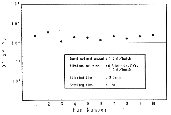
Fig. 2. Decontamination factor of Pu
in Alkaline washing treatment.
INCINERATION TREATMENT APPARATUS
As shown in Fig. 1, the incineration treatment apparatus consists of a adjustment tank, a feed pump, an incinerator an exhaust gas filter and a mixer for cementation. Main devices are installed in the hood (capacity of 80m3).
Propane gas was used for ignition and flame temperature was measured by infrared ray and combustion condition was observed by 1TV. A flame-eye-monitor was installed for emergency interlock. Incinerator was horizontal type and covered with reflect bricks. The treatment capacity of this incinerator is 3.1L/h.
A high temperature honey-comb ceramic filter (max. 550°C) was installed in the exhaust gas filter to collect the incinerator ash. Average pore of the ceramic filter is 9 to 14 µm in diameter. The adhered incineration ash was blown away by back blow.
INCINERATION TREATMENT PROCESS
The washed spent solvent is transferred into the adjustment tank together with soluble calcium octylate in the ratio of 1:1.1. The n-dodecane (10% volume of the mixed solvent) is added to the mixed solvent in order to improve the incineration efficiency. The mixed solvent is stirred and transferred into the incinerator.
Corrosive phosphoric acid and generated by combustion of TBP reacts with calcium octylate quantitatively and converts into stable calcium phosphate powder (incineration ash). The incineration ash is recovered by back blow procedure after collecting by the ceramic filter.
This procedure is automatically performed by compressed air (5kg/cm2) every an hour on each ceramic filter during the operation.
Then the incineration ash is manually recovered from the bottom of the exhaust gas treatment device and solidified in cement in the ratio of 1:1:2 (ash: cement: water.)
RESULTS OF THE INCINERATION TREATMENT
It was turned out that operating temperature is maintained at about 1100°C during the incineration and that the off gas is lowered to about 360°C at the outlet of the incinerator and about 160°C at the inlet of the off gas filter after cooling by air. Those temperature of the incineration is less than the designed values.
Figure 3 shows the variation at the outlet temperature of incinerator, the inlet temperature of the off gas filter and the differential pressure of the ceramic filter and the incinerator during the operation. A rise in the differential pressure of the ceramic filter indicates that the ceramic filter is gradually choked. In spite of automatic back blow procedure every an hour, the differential pressure of the ceramic filter rises to about 320 mm H20 after operating for about 6 hours.
Because the interlock starts at 400 as H20, the differential pressure of the ceramic filter must be dropped by the back blow procedure after a night. Therefore the differential pressure of the ceramic filter dropped to the initial pressure as shown in Fig. 3.
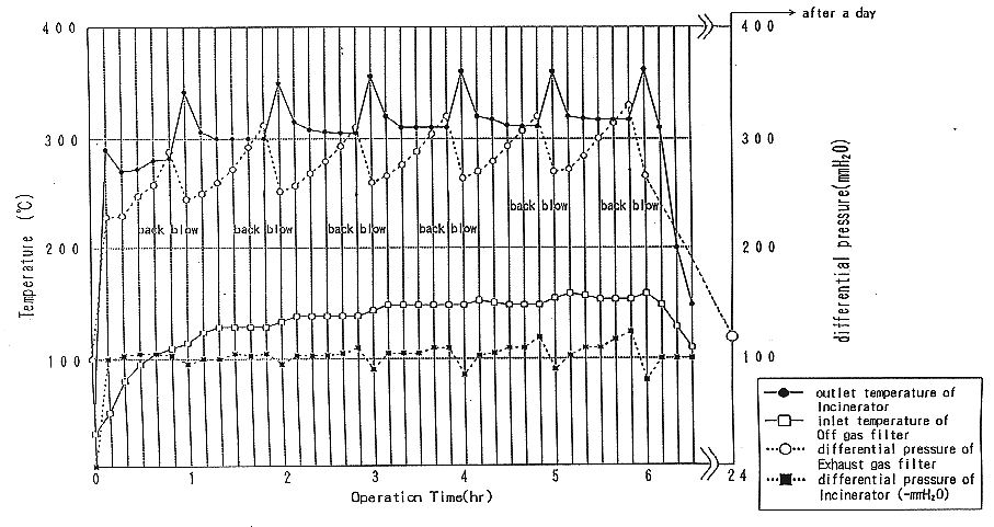
Fig. 3. Results of incineration
treatment for washed spent solvent.
187kg of the recovered ash is approximately equivalent to 180 kg of the calculated value.
3kg/batch of the incineration ash is solidified in cement in the ratio of
1:1:2 (ash: cement: water) and transported to the JWTF as
![]() •
•
![]() solid waste.
solid waste.
The loss of burning and the incomplete combustion were observed during the operation using ITV camera.
As the results of overhauling a main burner, it was confirmed that those problems are occurred by blocking up a tip of the burner with tarry matter. So the counterplan was done against these problem as follows.
ANALYSIS OF THE INCINERATION ASH
The ash adhered to the ceramic filter was collected for elemental analysis. results were shown in Table III and the following items were proved.
Table III Comparison of Analysis for Incineration Ash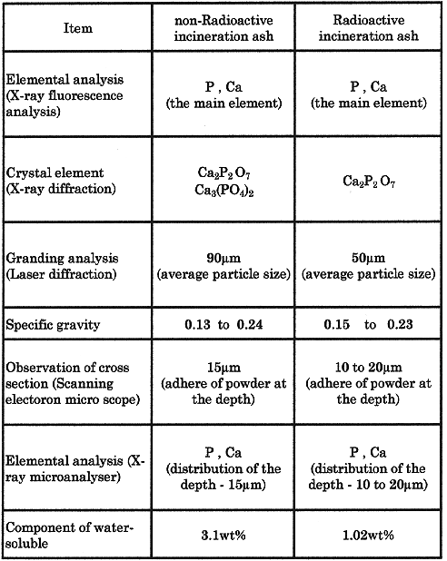
OFF-GAS SAMPLING APPARATUS
The off-gas sampling apparatus was designed to measure the radioactive concentration for each measurement points on same temperature and velocity conditions. As shown in Fig. 4, sampling points were located at the inlets of ceramic filter and off-gas HEAP filter, and outlet of off-gas HEAP filter. After passing the dust collector, the off-gas was collected by each off-gas collector using alkaline absorber. The radioactive concentration was calculated by the weight of the collected dust and the radioactivity of the liquid by the off-gas collector.
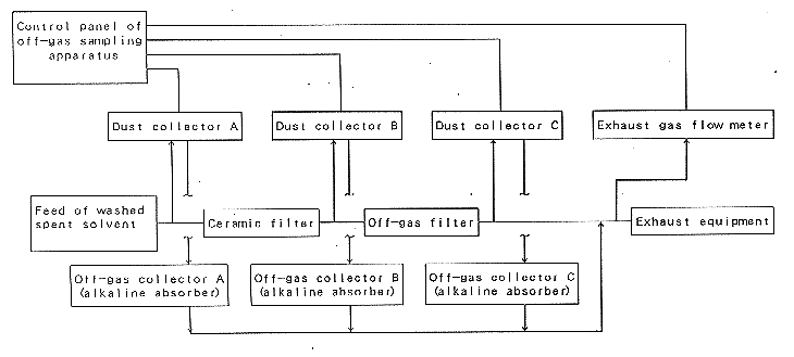
Fig. 4. Block flow diagram of off-gas
sampling apparatus.
EVALUATION OF RADIOACTIVITY
Evaluation was performed with two cases, immediately after the exchange of
the ceramic filter and the 188 hour operation of the ceramic filter. Six samples
were taken from the dust collectors A, B and C and the off-gas collectors A, B
and C. Because
![]() -ray
was adsorbed by the incineration ash, the analysis of
-ray
was adsorbed by the incineration ash, the analysis of
![]() -nuclides
was not evaluated correctly. So only the analysis of 7
-nuclides
was not evaluated correctly. So only the analysis of 7
![]() -nuclides
was performed. The results of analysis is shown in Table IV.
-nuclides
was performed. The results of analysis is shown in Table IV.
Table IV Radioactive Balance of Incineration Apparatus

89% (immediately after the exchange of the ceramic filter) and 84% (after the 188 hour operation of the ceramic filter) of the fed radioactivity were detected at the inlet of the ceramic filter. In each case, it was considered that the remaining 11% and 16% of the radioactivity were mainly stored in the incinerator.
The amount of radioactivity at the dust collector B and C was less than the limit of detection. Radioactivity was not detected from the off-gas collector A, B and C.
WASTE GENERATION
Amount of waste generated from the spent solvent treatment is shown in Fig. 5 1.2m3 of the spent solvent was separated into the washed spent solvent and the spent washing solution. The spent washing solution was treated by the TRU waste Treatment Apparatus (TWTA). The washed spent solvent was treated by the incineration treatment apparatus. 187kg of the incineration ash was generated and solidified with cement in the 10L -stainless steel container. Sixty-three containers were generated and stored in the JWTF.
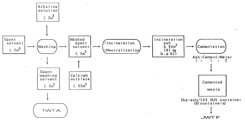
Fig. 5. Amount of waste generated
from the spent solvent treatment process.
CONCLUSION
Pu decontamination factor by washing treatment using sodium carbonate was more than 1000. Though sometimes the loss of the incomplete combustion were occurred by the accumulated incineration ash, the incineration and the cement solidification treatment ware carried out as schedule to make various improvements in the apparatus. Also, though the recovery of ash for each batch varied slightly, the total amount of recovered ash was approximately equivalent to the calculated value.
In the analysis for incineration ash, the element of radioactive ash was the same as the non-radioactive ash.
The treatment of spent solvent stored in the JRTF was completed in 1995. It was confirmed that the apparatus was efficient and useful for the treatment of the spent solvent. This process will has a wide application by scale up of system.